Introduction:
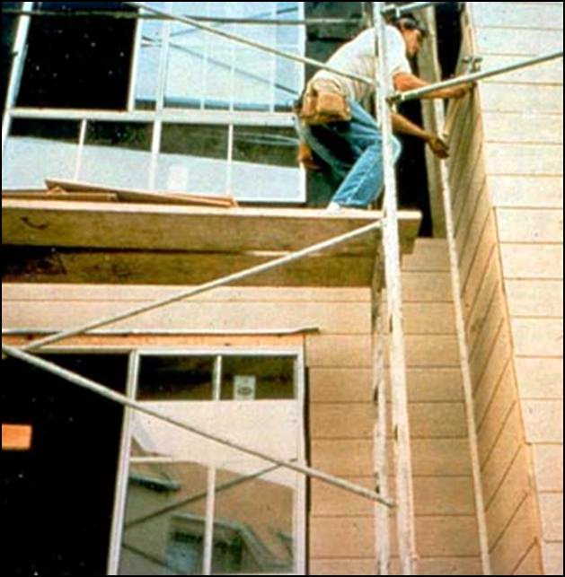
Scaffolding is a temporary structure installed against the side of a building, around a chimney, etc. to provide platforms for workers and materials during construction, maintenance, etc. Although there are many varieties of scaffolding systems, a common one is called independent tube and coupling scaffolding – popular because it transports efficiently, erects intuitively, and breaks down easily. Other scaffolding designs are used inside facilities for worker access to overhead equipment, for painting, etc. These designs are usually limited in height but have other features such as the ability to fold or telescope. Still, other scaffolds are available for specialized tasks such as building aircraft.
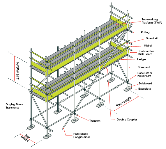
Scaffolding must adhere to OSHA standards for performance requirements and structural design methods. Because scaffolding must be compatible with a wide array of buildings and structures, there are numerous kinds of scaffolds to meet specific building requirements. However, scaffolding generally comprises some basic elements, though the manner in which they are designed and the way such elements fit together can vary.
Scaffolding contains the following parts:
1. Base plate
2. Sole plate
3. Standards
4. Ledgers
5. Transoms
6. Bracing
8. Platform/Decking
9. Clamps standard: EN-74 and BS-15.
10.Toe board should be minimum 6 inches in height.
11. Guard rails (Hand rails and mid-rails) height approximately 1 meter.
12. Working platform
13. Ties
14.The ladder shall be secure at three locations.
15.Tags either green or red tag and shall be renewed after one week.
Base Plate:
A flat supporting plate or frame at the base of a column, designed to distribute the column's weight over a greater area and provide increased stability.
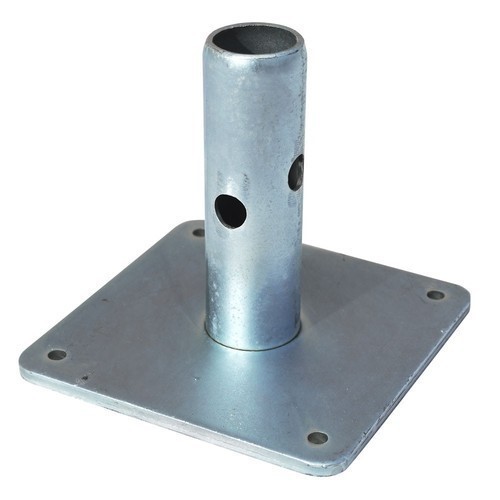
Scaffold Base Plate is a foot plate for scaffold systems of Ring lock Scaffolding, Kwik stage Scaffolding, Cup lock Scaffolding, Scaffolding Frames, Tube and Clamp Scaffold. Socket Base Plate is used to as Socket of Universal Jacks, Scaffold Poles. Base Plate is Mainly Used to Spread The Load Onto The Sole Plates.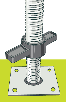
All uprights or standards of a scaffold are to be mounted on a steel base plate. The thickness of the steel base plate shall be a minimum 6mm and size shall be of 150 mm x 150mm. Irrespective of the supporting ground condition or concrete surface, the base plate is to be used mandatory.
The purpose of the mud sill under the scaffold base plate is to uniformly distribute the scaffold load over a larger area than that distributed by the base plate alone, thereby reducing the loading on the ground beneath the base plates.
Types of Base Plate
- Flat Base.
- Angle Flat.
- Ribbed or spigot.
A minimum thickness of 12 mm is recommended for posts and lightly loaded columns, while 20 mm minimum thickness is recommended for normal applications Preferred plate thicknesses for the base plate are: 12, 16, 20, 25, 28, 32, 36, 40. Base plates are typically cut to size using thermal processes.
Sole Plate:
A timber spreader used to distribute the load from a base plate to the ground. Tie Scaffold components installed to provide an anchor point for a scaffold to a building or structure, including tie tubes attached to the scaffold. Used to provide lateral stability to the scaffold.
The sole plate, also sometimes referred to as the sill plate, the mud sill, or the base plate, is the main supporting beam of a wall in the construction industry. Typically, these are the first piece of wood that is in contact with the masonry of the basement or foundation.
- Sole boards must be a minimum of 450mm x 225mm x 35mm but the size may need to be increased depending on leg loads and/or ground conditions.
- Base plates and sole boards must be provided on, level ground and must be able to be inspected at all times.
A timber or metal barrier to distributing the load from a standard or base plate to the ground and prevents the sinking of the scaffold. The width and thickness of a timber sole plate shall be 200mm and 25 mm minimum. In place of timber soleplate, 10 mm thick steel plate or steel channel of size more than 200mm depth (ISMC 200) with flanges facing upward, may also be used as the soleplate.
The soleplate area shall not be less than 1000 sq.cm. Sole plates should be long enough to hold at least two vertical pipes and should extend 600 mm beyond the vertical pipes. Sole plates may be avoided in case the scaffold is erected on the firm ground like the concrete floor.
Difference between sole plate and base plate in scaffolding:
BASE PLATE / JACKS - to safely carry and spread the load. A metal plate with a spigot for distributing the load from a standard or raker or other load-bearing tube.
SOLE PLATES - A timber, concrete or metal bearer used to distribute the load from a standard or base plate to the ground.
Standards:
A standard is the long pipe or tube running vertically that connects the mass of the scaffold directly to the ground. The base of each standard is connected to a base plate, or sill, which helps distribute the weight each standard bears. As standards are of fixed lengths, taller scaffolding requires that the pipes be connected so as to route the load directly through the structure. This is accomplished by way of a pin and socket joint which twists to lock successive pipes together.
Pairs of standards are placed at the back of the scaffolding (nearest the building) and at the front of the scaffold, the two pairs of standards forming a bay that has a width (back-to-front dimension) and length (side-to-side dimension).
The standards, also called uprights, are the vertical tubes that transfer the entire weight of the structure to the ground where they rest on a square base plate to spread the load.
Tubes are usually made either of steel or aluminum; although there is composite scaffolding which uses filament-wound tubes of glass fiber in a nylon or polyester matrix, because of the high cost of composite tube, it is usually only used when there is a risk from overhead electric cables that cannot be isolated. If steel, they are either 'black' or galvanized. The tubes come in a variety of lengths and a standard outside diameter of 48.3 mm. (1.5 NPS pipe). The chief difference between the two types of metal tubes is the lower weight of aluminum tubes (1.7 kg/m as opposed to 4.4 kg/m). However they are more flexible and have a lower resistance to stress. Tubes are generally bought in 6.3 m lengths and can then be cut down to certain typical sizes. Most large companies will brand their tubes with their name and address in order to deter theft.
Galvanized steel scaffold tube is the main scaffolding part which creates the framework and the base for working platforms. Scaffold tubes are made from galvanized steel, are heavy duty and come in various lengths ranging from 5ft to 21ft and all have a different part to play.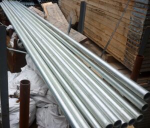
In general 21 foot or 6.4 meter tubes are used as the upright standards and these are one of the main components that connects most of the scaffolding together. Standards are placed in a vertical position from the ground up on to a baseplate which is a scaffolding part that helps spread the weight.
For general scaffolding works e.g. painting and decorating, each upright standard should be placed a maximum of 2 meters apart. For heavy duty works where there is a heavy load going to be placed on the working platform then the standards should be a very maximum distance of 1.8 meters apart and this is generally called the bay length.
If you are looking to erect scaffolds higher than 21ft then the standards would need to be connected on top of one another using a joint pin scaffolding part which is inserted into the inner tube which then locks the uprights together.
To create a scaffolding bay you would need the following scaffolding parts, two pairs of standards, one should be close to the building and is usually referred to as the inside standard or upright. The next standards would be placed directly opposite the inside uprights and are usually called the outside standards which then creates the bay. The width and length dimensions of each bay may vary depending on what types of scaffold you require.
Thickness of tubes: measure the inside wall and regardless of the length most galvanized tube measures in at 4mm in thickness.
Scaffolding tubes diameter: you need to measure the outside of the tube from edge to edge. You will find most type 4 tubes no matter what length they are have a diameter which is usually 48.3mm or 1.90 inches.
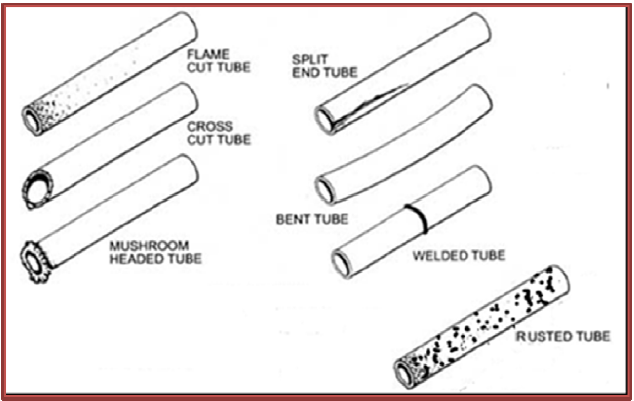
STANDARD-DIFFERENT TYPE OF DAMAGES
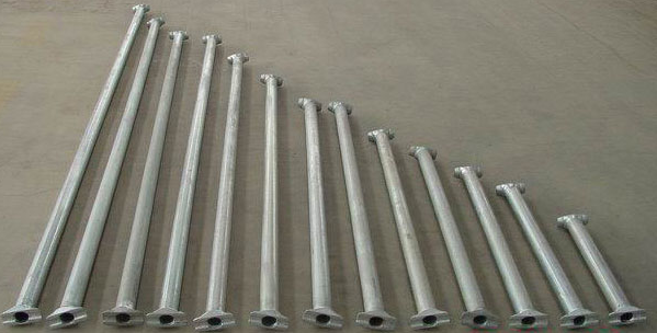
The galvanizing process: is pretty simple, when the poles are manufactured the metal is sealed from all corrosion and oxidation. The steel poles are hot dipped in to a bath of molten zinc at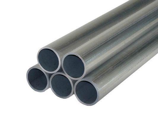 temperatures exceeding 800 degrees Fahrenheit adding a bonded coating to the steel for extra protection.
These poles have been put through the galvanizing process to ensure that they are environmentally friendly and also strong and hard wearing, resistant to rust and have an increased life span. Buying steel scaffold tube is slightly more expensive than other poles available and this is due to the galvanizing, however you will save your money in the long run as these steel tubes will require far less maintenance or replacing.
Every Scaffold and every member or component thereof shall be:
- Metal having adequate strength & Free from defects
- Suitable and safe for the purpose for which it is intended.
- Scaffold Supervisor shall carry out monthly inspection of all the materials required for scaffold and
- immediately replace the damaged materials, if any.
- HSE coordinator shall carry out quarterly audit of Scaffold Material along with Scaffold Supervisor.
- Scaffold Contractor has to change the Scaffold material if when asked by the HSE department.
- Flame cut tube, Cross cut tube, Mushroom Head Tube, Spilt End Tube, Bent Tube, Welded Tube, Rusted Tube, not consider as a scaffold tube. Refer to below image
Ledgers:
In between each standard, running horizontally along the length of the scaffold, is a ledger or runner or cross beam, which adds further support and weight distribution. Multiple bays are connected with these ledgers both at the back and the front of the scaffold. Placement of ledgers defines the height at which the worker platforms are staged (except for the lowest one which is placed near the ground).
Joints in ledgers should also be staggered, i.e. joints in adjacent ledgers should not occur in the same bay. These joints should be made with sleeve couplers and not be more than one-third distance away from a points in ledgers on the same lift and in adjacent lifts should not occur in the same bay unless there is unjointed guardrail (not to be removed) when joints in the ledgers above and below can be in the same bay.
The spacing of ledgers (lift heights) will be:
independent tied scaffolds – 2.0m
putlog scaffolds – 1.35m
Some types of system scaffold do not require ledger/cross bracing unless:
- ties cannot be located as required by the manufacturer or are liable to be removed; or
- the height of the scaffold is 4m or more above the last line of ties.
Where ledger bracing is installed for the above reasons, the loads on the adjacent ties will be increased. The system manufacturer’s instructions should be consulted to determine whether ledger bracing is required.
Ledger bracing should be installed on tube and fitting scaffolds. Brace alternate pairs of tube and fitting standards, ensuring that the bracing forms a complete series of triangles from bottom to top of the scaffold. Install the bracing from ledger to ledger or from standard to standard. For tube and fitting scaffolds, brace each pair of standards where the bracing is installed from the inside ledger to the guard-rail of the lift below to allow access along a boarded lift.
When clear access is required on base lifts of tube and fitting scaffolds, the cross bracing may be omitted on the base lift provided the first lift does not exceed 2.7m, or the lift is knee braced. In either case, the loading capacity of the scaffold will be reduced.
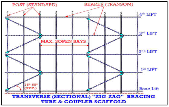
Transoms:
Transoms or bearers, placed on top of ledgers and at right angles to them, run horizontally from back to front, defining the bay width. Main transoms provide support for standards by holding them in position as well as supporting boards or planks. Intermediate transoms are placed alongside main transoms to lend additional board support.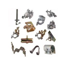
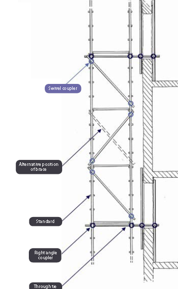
In addition to standards, ledgers, and transoms, there are several other supportive elements that serve to reinforce the fundamental scaffolding. Braces include cross, or transverse, braces and façade, or longitudinal, braces. Cross braces run diagonally between ledgers and securely attach to standards to increase a structure’s overall rigidity. However, they can also be secured between ledgers, in which case they are simply called ledger braces. Façade braces help prevent a structure from swaying and are attached on the face of the scaffold, running diagonally along the length of the structure and securely attaching at every level. They are attached along the back of the scaffold as well.
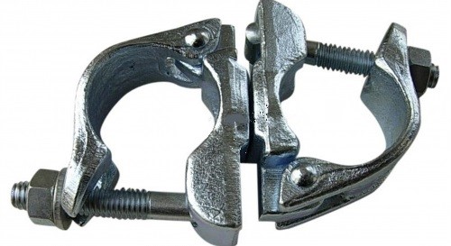
Couplers help connect structural elements and come in several variants. To connect a ledger or transom to a standard, a right-angle coupler is used. If a transom supports a board and must be connected to a ledger, a putlog or single-coupler is used to connect the ledger to the transom. For any other angle of connection between scaffold piping, a swivel coupler is recommended.
Transoms are secured to ledgers with either right angle or putlog couplers unless braces are secured to them, in which case only right-angle couplers are acceptable. On boarded lifts, transoms will be spaced to ensure adequate supporting of the scaffold boards overlap 50mm over the transom. On non-boarded lifts and transoms should be secured at not more than 300mm from each standard or pair of standards.
Transom Beam: In scaffolding. A beam spanning a wider gap between standards than normal. Usually where wider access is required at ground level for vehicles and equipment. In modular systems they only have one attachment point each end to the standards.
Transom Truss :In scaffolding. A beam spanning a wider gap between standards than normal. Usually where wider access is required at ground level for vehicles and equipment. In modular systems they are deeper than transom beams and so have two attachment points at each end to the standards.
![]()
Above is a shot of a break in a scaffold to allow access to the inside of the building. It is spanned by two rather tired looking beams (at the bottom) and beefed up by two ladder beams (above) fixed to the standards with couplers.
![]()
Bracing
No scaffold can remain stable or safe unless properly braced. Bracing should remain in position at all times to ensure this stability. There are two main types of bracing, as follows:
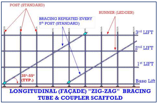
Façade Bracing:
These are used to stop the framework from moving or swaying. They are attached to the front face of the structure and run along the length of the frame in a diagonal position and are fixed securely on every platform. This type of bracing should be installed every forth bay as well as the first and last bays, so the space between the braced bays is a maximum of three bays.
All bracing points should be 300mm off the connection node joint of the standards, transoms, and ledgers.
Fixed to the long face of the scaffold normally parallel to the face of the structure and is fitted to the outside row of standards. It can either run across the face of the scaffold to its full height at an angle of 45° or run in a zig-zag fashion to its full height.
Bracing should be provided at least every 3.0m along the scaffold. Bracing will be fixed to extended transoms with right angle couplers or to standards with swivel couplers. Where braces are fastened to transoms, the transoms should be fixed with right-angle couplers, (load-bearing) to the scaffold. Brace couplers may be used as an alternative.
Cross or transverse brace:
This type of brace is mainly run diagonally in between the inside ledger and is fixed to the outside standards using a swivel coupler to boost the frameworks firmness. They can also be fixed ledger to ledger on the lifts above the base out. This brace should be added to every other bay or every other set of standards.
Fixed to join inner and outer alternate pairs of standards, fixing is by using right angle or brace couplers connected to the ledger or with swivel couplers to standards.
When a bay length is 1.5m or less, the bracing may be fixed to every third pair of standards. On boarded lifts, the brace would be fixed under the outside ledger to the inside ledger of the lift below to avoid the toe board. Bracing may be fixed from the inside ledger to the guardrail level of the below provided that every pair of standards are braced.
Platforms/Decking:
Platform/decking planks may be made of solid sawn wood, manufactured wood, manufactured steel, or manufactured aluminum. If solid sawn wood is used, it must be scaffold grade.
- Note: Once a plank has been used as a mud sill, it cannot be used as decking again.
Scaffolds must be fully planked or decked whenever possible. The space between the last plank and the uprights cannot exceed 9 1/2 inches. The space between planks cannot exceed 1 inch, except where necessary for obstructions. Platforms and walkways, in general, must be at least 18 inches wide.
 Where the platform will not be more than 14 inches from the face of the work (18 inches for plastering and lathing operations), fall protection is not required. The face of the work (ex. the side of a building) basically serves as the fall protection system.
The ends of each platform must be cleated or restrained by hooks (or equivalent) to prevent accidental displacement, or must extend at least 6 inches over the centerline of the support.
- The maximum extension of the plank cannot be more than 12 inches for planks that are 10 feet long or less.
- For planks that are greater than 10 feet long, the maximum extension past the centerline of the support is 18 inches.
- Where platforms overlap to create a running scaffold, the overlap must occur only over a support and shall not be less than 12 inches unless nailed together.
Where a platform changes direction (ex. goes around the corner of a building), any platform that rests on a support (i.e. bearer) at an angle other than a right angle, shall be laid first. Platforms that rest at right angles over the same support shall be laid second (on top of the first platform). The objective is to reduce the tripping hazard by having the ends of the top layer of planks form a straight line, rather than a saw-toothed edge, which increases tripping hazards.
Wooden platforms (i.e. decking, planks) must not be painted to hide defects. They may, however, be treated periodically with clear preservatives, fire-retardants, and/or slip-resistant finishes.
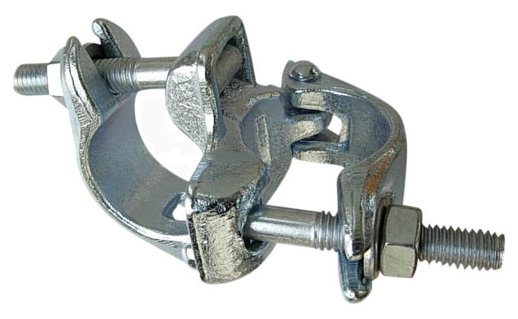
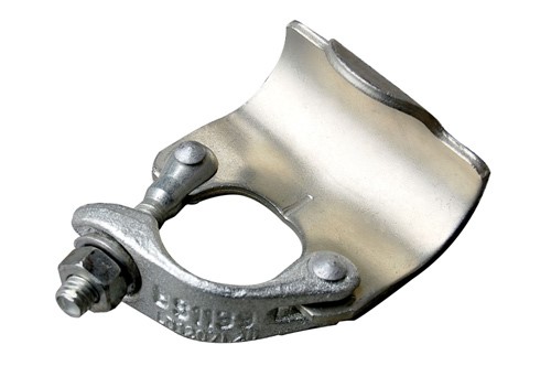
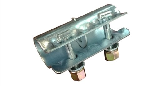
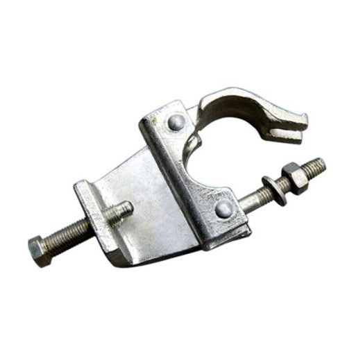
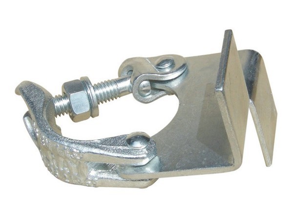
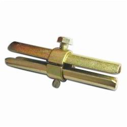
Couplers and clamps:
Scaffold couplers are essentially the fundamental component that is used to assemble tube-and-coupler scaffolding. Tube-and-coupler scaffolding is defined as ‘a scaffold in which individual circular tubes serving as standards, braces or ties are joined together by means of purpose-designed couplers’.
This basic fitting that is designed to join two scaffold tubes can be used to create a diverse range of scaffolding structures or used as an accessory to prefabricated scaffolding systems.
These components are classified into two categories – load-bearing and non-load bearing.
Load bearing couplers or components are: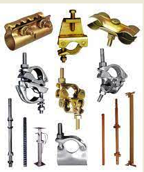
- Right angle couplers
- Swivel couplers
- 5 KN brace couplers
- Adjustable fork heads
- Adjustable base plate jack
Non-load bearing couplers or components are:
- Expanding joint pins
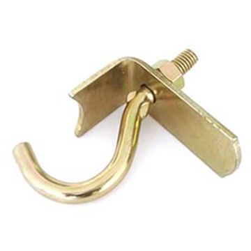
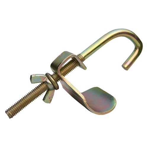
- Toe board clips
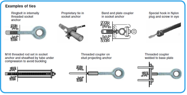
Ties:
Ties connect the scaffold to the structure being built. Ties perform a dual function:
- they stabilize the entire scaffold to prevent it from falling towards or away from the building; and
- they stabilize the individual scaffold standards to prevent them from buckling. As the load on a
scaffold increases, more ties may be needed to prevent the standards from buckling.
There are several different tie types. Those types of tie that are non-movable should be chosen,
where reasonably practicable, as they present fewer difficulties with maintenance or interference. Non-movable ties are assumed to be cast or drilled into the structure and will not need to be moved until final dismantling of the scaffold.
Ties should resist movement towards the building and away from the building. Where a tie cannot
resist movement towards the building, e.g. through ties, long bolts and wire ties, the tie should be supplemented by other measures, e.g. tubes butted against the building.
Ties should be securely coupled to both standards or to both ledgers, in accordance with the manufacturers recommendations, and be as near to a node point as possible. Where ties are attached to the ledgers, they should be attached not more than 300mm from a standard. Where this hinders access along a working platform, attachment to the inside ledger or standard only is permissible.
The vertical interval between ties should be determined in the scaffolding design and communicated to the scaffolding erector. In the case of system scaffolds, reference should be made to the manufacturer’s instructions.
Scaffolds of normal width of 1.25m should not be erected higher than the manufacturer’s instructions and to a maximum of 4m higher than the highest line of ties, unless to a specific design.
Working platform:
Working platforms should be wide enough and be sufficiently boarded out to allow safe passage of
persons along the platform. They should also be capable of resisting the loads imposed upon them,
including high wind loads that could dislodge the scaffold boards. The contractor in control of the
workplace must risk assess for potential adverse weather conditions.
Where a person could fall a distance liable to cause personal injury, the working platform should be
of the widths. A clear passageway, at least 450mm wide, should be maintained for persons to pass between stored materials and the side of the platform. They should be kept free from construction materials and waste to avoid causing an obstruction or a trip hazard.
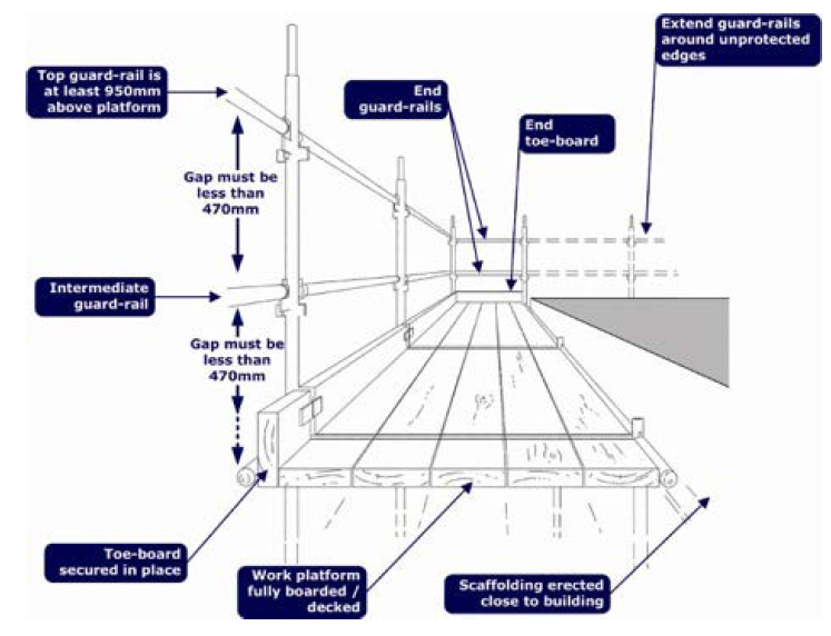
Guardrail Systems:
A fall protection system (i.e. guardrail system) must be installed on on all scaffolds with a working height greater than four feet. The guardrail system shall be installed along all open sides and ends of the platform before being used as a work platform by employees. One exception is when the scaffold platform is within 14 inches of the face of the work.
Top rails (manufactured after 1/1/2000) must be 38 - 45 inches above the platform surface. (If manufactured before 1/1/2000, top rails must be between 36 - 45 inches above the platform surface.) Top rails must be capable of supporting at least 200 pounds applied in a downward or outward direction.
Mid rails must be installed at a height approximately midway between the top rail and the platform surface. Mid rails must be capable of supporting at least 150 pounds applied in a downward or outward direction.
- Guardrails will be installed on every platform from which it is possible for a person to fall.
- Guardrail system shall be able to withstand a force of at least 90kg. (200 lbs.) It consists: (As per OHSA Guide lines)
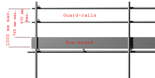
- The minimum permitted height is 950 mm (37 inch) and the maximum is 120 mm (47 inch) as measured from the top of the working platform.
- Mid rails – installed approximately halfway between the walking/working surface and top rail.
- Guardrails shall be installed on all sides of a working platform.
- Guardrails shall be fixed to the inside of the standards with right angle (Double) couplers.
- All toe boards must be placed on the inside of uprights
- Every open side of a working platform will be fitted with toe boards (or other barriers) which must be a minimum of 150 mm (6 inch) high.
- Toe boards must be fixed to all exposed edges where there is risk of fall or risk of falling materials. There should be no gaps larger than 25 mm (1 inch) other than at access points.
Toe boards
Toe boards must be installed on work platforms where materials or tools will be in use. Toe boards must be installed not more than 1/4 inch above the platform and securely fastened. They may be made of solid material or mesh with openings no greater than 1 inch. Toe boards must be capable of withstanding at least 50 pounds applied in a downward or outward direction.
Nets and Platforms
Additional protection from falling debris and other small objects must be provided in areas where personnel will be in the vicinity of scaffolds. Such protection may be in the form of:
- Barricades to keep personnel out of a hazardous area,
- Screens which are erected between the toe board and hand rail of the work platform,
- Debris nets to catch materials before they hit the ground, or
- Canopy structures made of solid materials.
Large or heavy materials stored on the scaffold platform must be located away from the edges of the work platform and secured, if necessary.
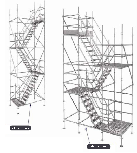
Ladder access:
Scaffold access ladders should meet the following minimum standards:
- ladder access towers, fixed to the outside of the scaffold, should be erected, where practicable using single lift ladders and self-closing ladder gates to separate the access tower from the working platform;
- the top of ladder stiles should be securely fixed to the scaffold by lashings;
- the ladder should be set, where practicable, at an angle of not more than 4 vertical to 1 horizontal and allow sufficient room for workers access and egress through the ladder access opening;
- each stile should be equally supported on a firm and level footing;
- the ladder should extend at least 1m above the landing point unless a suitable alternative handrail has been provided;
- the maximum vertical distance between landings should be 9m;
- where the ladder is internal, guardrails or other protective measures should be in place around the
opening to prevent someone stepping into the ladder access opening accidently; - the clear dimensions of an access opening in a platform shall be at least 450mm wide, measured
across the width of the platform, and 600mm long;
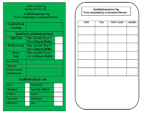
Scaffold Inspection & Tag:
Subject to provisions of this regulation no scaffold shall be used unless:
- It has been inspected by a qualified and authorized safety engineer before using; also it has been inspected by a trained and qualified scaffold inspector.
- Before the scaffold is first used
- At least once every 7 days
- After any modifications to the structural components of the scaffold.
- After any severe weather that may have damaged the scaffold
- All scaffold inspections will be recorded on the Scaffold tag and in the scaffolding register on the day of the physical inspection
- Scaffolds that are approved as safe for use by the scaffold inspector will be have a GREEN tag placed at each access point to clearly show the scaffold users that the scaffold is safe to use.
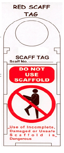
- Scaffold Read Tag - Indicates the scaffold has not been inspected or is not safe for use (by anyone other than the scaffold erector.
- Scaffolds that do not have a tag must be considered to be RED tagged and must never be used.
- Visually inspect the scaffold before you use it, if your believe it to be unsafe in any way inform your supervisor before using the scaffold.
- Never replace, remove, add or alter a scaffold tag in any way, this is the sole responsibility of the scaffold inspector.
- Never alter or modify scaffolding in any way, this includes modifications to handrails and toe boards. Only trained and approved scaffolder may alter or modify scaffolding in any way.
- Never climb bracing or climb under or over a guardrail of any type to gain access onto or off of a scaffold. Keep only the tools and materials necessary to perform the task on the platform. Control slipping and tripping hazards by removing or securing tools or materials.
- Use fall protection systems when working 1.8m (6feet) or more above a lower level.
- Maintain a clean and tidy work area on the scaffold; do not allow loose materials to build up on the platforms and remove all tools and materials that are finished at the end of your shift.
- Never use a scaffold as a lifting support unless it has been designed for that purpose, check with your supervisor if you are unsure.
- Never store materials near the edge of a scaffold higher than the height of the toe board.
Click the below link to download more details about scaffolding safety

OSHA Fact sheet - Scaffold tubes, coupler, plan & designing
Safety check sheet - Scaffolding- 1
Safety check sheet - Scaffolding- 2