Excavation work is hazardous. This guideline provides information on the potential hazards involved in excavation work so that workers and employers can work together to create a safe, injury and fatality free work site.
DEFINITIONS: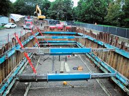
Excavation: means a dug out area of ground and includes a deep foundation excavation, trench, tunnel and shaft.
Open excavation means an excavation in which the width is greater than the depth, measured at the bottom.
Trench means an excavation that is deeper than its width measured at the bottom.
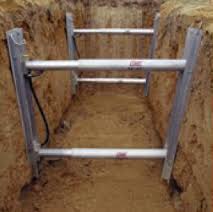
Trench Cage means a steel support structure designed to resist the pressure from the walls of a trench and capable of being moved as a unit.
Trench Jack means a screw or hydraulic jack used as a brace for a temporary support structure.
Shoring is an assembly of structural members designed to prevent earth or material from falling, sliding or rolling into an excavation.
Pile or Caisson means a slender,deep foundation unit made of materials or a combination of materials, such as wood, steel or concrete, which is either pre-manufactured and placed by driving, jacking, jetting or screwing, or cast in place in a hole formed by driving, excavation or boring.
Shaft means a vertical or inclined opening that leads to an underground working and is excavated below ground level.
Support structure means a temporary/permanent structure or device designed to provide protection to workers in an excavation, tunnel or shaft from cave-ins, collapse, sliding or rolling materials and includes shoring, bracing, piles, planks and trench cages.
Tunnel means a generally horizontal excavation that is more than a metre long and located underground.
HAZARDS TO WORKERS NEAR EXCAVATION SITES:
The most common hazards that exist in excavation work include:
- cave-ins or excavation collapses
- excavated material
- falling objects or objects near an excavation
- powered mobile equipment
- slips, trips, and falls
- hazardous atmospheres
- flooding/water hazards
- underground facilities
Cave-Ins or Excavation Collapses:
It is because both employers and workers often forget that when they remove earth from the ground it creates an opening, and the remaining earth surrounding the opening tends to relax. This increases the pressure towards the walls of the opening and makes the ground collapse. Water in the soil or ground also affects the stability of the walls by putting additional pressure on the walls & increasing the possibility of a cave in. Unless a horizontal distance equal to the vertical depth of the excavation walls is maintained, engineering controls must be used (ex: shoring, trench cages) to provide a safe and healthy workplace within the excavation area.
Excavated Material:
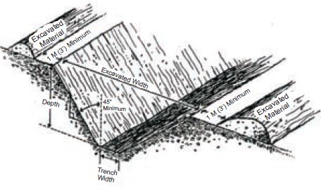
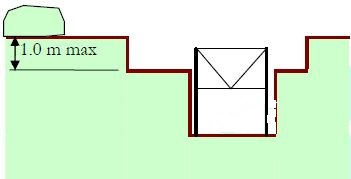
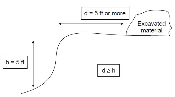 Injuries may also occur in excavation work when excavated material on the surface of the excavation is too close to the edge and falls into the excavation, or affects the structural stability of the walls of the excavation. Pile all excavated material so that the material cannot roll back into the excavation. The material must never be closer than one metre (three feet) from the edge of the excavation, and should be placed as far away as possible so it does not affect the structural stability of the walls. Ideally, the excavated material should be placed as far away from the edge of the vertical excavation as the excavation's height (d ³ h: see diagram below).
Falling Objects or Objects near an Excavation:
Place tools and equipment used at the excavation site so that they cannot fall into the excavation or affect the structural stability of the walls of the excavation. Use barriers to help keep tools and equipment at a safe distance from the edge of the excavation. Use ropes or other lowering devices to transport the tools or equipment into the excavation.
Powered Mobile Equipment
Workers may be exposed to hazards when powered mobile equipment is used near an excavation site. Powered mobile equipment includes backhoes, track hoes, concrete trucks, trucks removing excavated material and others. Common hazards related to powered mobile equipment include:
- equipment placed close to the edge of an excavation may cause the excavation walls to
 become unstable. Powered mobile equipment can be placed near the edge of the excavation if a support structure, designed to consider the overload from the equipment, is installed in the excavation.
- equipment vibration puts additional pressure on excavation walls, affecting the structural stability.
- equipment operating on rough terrain, or too close to the edge of an excavation, may roll over and fall into the excavation. Ensure all equipment is equipped with roll over protective structures (ROPS).
- workers riding on equipment without approved seats may be injured.
- workers getting on and off equipment are at risk because balance can be affected by the vibration of the equipment. A worker may not be as sure footed getting off the equipment after operating it for a period of time.
- workers may be injured by equipment. A safe distance must be maintained from moving equipment at all times. Operators must be aware of all workers near their work area.
Slips, Trips, and Falls
Slip, trip and fall hazards are common around excavations. Examples include:
excavation entrances and exits. A safe means of entering and exiting an excavation is required. Specifically, where an excavation is more than 1.5 metres (five feet) deep, a stairway, ramp or ladder is required. Workers must use both hands when climbing up or down ladders. Tools or equipment should not be carried up or down the ladder. In addition, the ladder must:
- meet the standards outlined in the Workplace Safety and Health Regulation, respecting Entrances, Exits, Stairways and Ladders.
- extend one metre above the edge of the excavation
- be located no more than three metres (10 feet) away from the workers inside the excavation.
uneven ground surfaces around or inside an excavation. It is important that a housekeeping program is in place and every effort is made to ensure walkways and pedestrian traffic areas are maintained.
Hazardous Atmospheres:
Hazardous atmospheres at excavation site may come from soils that are moved or from pipes and conduits disturbed during excavation. Where there is a potential for a hazardous atmosphere, a plan must be developed to ensure the workers in or near the excavation are not at risk. The plan must include the following steps:
Pre-Work Testing – The atmosphere must be tested before anyone enters the excavation to ensure they won't be exposed to hazards. Common atmospheric hazards include gasoline vapours, methane or other explosive gases and a lack of oxygen.
Periodic Testing – Periodic tests must be conducted to ensure the hazardous atmosphere is controlled and that workers are protected. All testing must be done by qualified personnel who have the knowledge and expertise required to keep workers safe. All tests conducted must be:
- recorded
- kept at the excavation site
- made available to the workers upon request
Flooding/Water Hazards:
Because of the condition or location of excavation sites, water hazards may be present, including:
Flooding – An excavation may flood if the work is below the water table, near a watercourse bank or exposed to adverse weather conditions. When there is a risk of flooding, an emergency evacuation plan must be developed. The plan will include a full body harness with a lifeline (that meets the
requirements of Part 14 of the Workplace Safety and Health Regulation, relating to fall protection) to be worn by workers in the excavation. Workers must also have direct communication with the person located at the surface of the excavation.
Water Accumulation – This may be caused by an excavation near a ground water source, in wet conditions or because of equipment that uses water for operation near the excavation site. Water accumulation must be kept to a minimum to reduce risks such as slipping or tripping hazards, electrical hazards, equipment malfunctions or others.
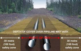
Underground Facilities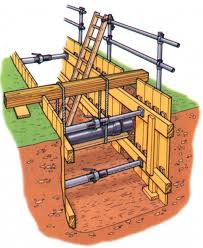
Common underground facilities include:
- electrical lines
- oil and gas lines
- telecommunication lines (phone, cable, computer)
- water and sewer lines
- traffic signal lines
- steam lines
Special attention must be given to the hazards associated with underground facilities. Before beginning excavation work, proper planning must identify the location of underground facilities and any precautions needed to avoid contact with these facilities.
SOIL PROPERTIES:
Category 1 – Cohesive soils of firm to stiff consistency that are fissured (Category 1b) or unfissured (Category 1a). These soils are generally of medium to high plasticity but may also include glacial clay tills of low to medium plasticity. These soils usually have low moisture content and most often occur above the water table.
Category 2 – Cohesive soils of soft consistency and non cohesive silt soils. The cohesive soils can be of medium to high plasticity while the silt soils are of non to low plasticity. These soils typically have high moisture contents and will tend to fill voids left between the excavation walls and shoring.
Category 3 – Cohesionless soils of loose to medium dense (Category 3a) and dense to very dense (Category 3b) consistencies. The Category 3a soils are generally easy to excavate by hand and are easily disturbed by construction equipment, particularly when they are at or near the water table or become saturated.Category 3b soils are generally not easy to excavate by hand and are not easily disturbed by construction equipment, except if they are at or near the water table or become saturated.
Soil Types:
Cohesive Soils:
Silty clay – soil of medium to high plasticity of primarily lacustrine origin. The silty clay can range from soft to hard depending on the moisture content and is usually brown in the upper six to 10 metrs and grey below indicating the extent of previous oxidation and weathering. Typically, the upper three meters of lacustrine clay is weathered, fissured and nuggety.
Alluvial Clay – soil of medium plasticity, although plasticity can range from low to high. Alluvial clay can vary greatly in grain size distribution and consistency, but generally, the major constituent of this soil type is silt, followed by clay and then sand. Alluvial clay can range from very soft to stiff,
depending on moisture content. In a dry state, the soil may often appear to be cohesion less, while in a wet state, alluvial clay is often very soft and subject to sloughing.
Glacial clay till – heterogeneous mixture of boulders, cobbles, gravel, sand, silt and clay, generally of low to medium plasticity.Glacial clay till can vary from soft to hard,primarily dependent on moisture content and deposition characteristics.
Cohesionless Soils: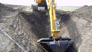
Silt – soil that is non-plastic to low plastic. Silt ranges from loose to extremely dense depending on moisture content and deposition characteristics. Silt is seldom encountered in a pure state, but normally has a significant fine sand component and occasionally a trace of some clay
Sand – sand can range greatly in grain size and density, and is often poorly graded (sorted). Typically, saturated sand exhibits a dilate behavior (fine grained sand), unstable with respect to excavations, and is subject to sloughing.
Gravel – like sand, gravel can have a wide range of grain size distribution and density. In a dry state, gravel is generally more stablethan sand (although still somewhat unstable) in vertical cuts, but still requires sloped excavation walls. Typically, on saturation, gravel becomes unstable (although less so than other cohesionless soils) with respect to excavation, and is subject to sloughing,
Glacial silt till – soil that is non-plastic to low plastic. Glacial silt till is a heterogeneous mixture of boulders, cobbles, gravel, sand, silt and clay.
Fill – fill can be a single soil type or a mixture of various soil types such as clay, sand, gravel, organic soils, etc. and may even contain non-soil materials such as demolition rubble or wood. It can vary widely in consistency, but is often softer or looser than the surrounding native soil, and has a greater likelihood of sloughing when encountered in excavations. In particular, it cannot be relied upon to be uniform, even over short vertical and horizontal distances, and may collapse in any one of several different modes, depending on its makeup.
Bedrock
The limestone and shale bedrocks are typically highly weathered and fractured when at or near the natural ground surface, but often become less fractured and more intact with depth.
The shale bedrocks are generally considered to be soft rock while limestone can vary from soft to hard. Generally, limestone bedrock is stable to very stable with respect to excavations or rock cuts. Similarly, shale bedrock can also be table to very stable but, in instances where the shale is fractured or contains existing failure planes, the shale can perform poorly.
Types of Soil Collapse:
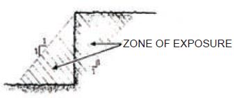
General Zone of Exposure
(the area where workers are exposed to mass soil or rock movement)
Collapse Type 1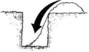
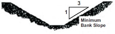
Spoil pile slide – improper excavating procedures occur when the excavated material is not placed far enough away from the edge of the excavation. The recommended minimum distance for location of excavated soil (spoil) from the edge of the excavation is equal to or greater than the excavation depth. However, the minimum permissible distance of spoil from the edge of the excavation is 0.6 metres for every one metre of excavation depth.
Collapse Type 2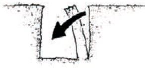
Side wall shear – common to fissured or desiccated clay-type or alluvial soils that are exposed to drying.
Collapse Type 3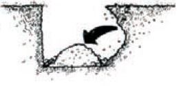
Slough-in (cave-in) – common to previously excavated material, fill, sand, silt and sand mix and gravel mix where the water table is above the base of excavation, or where soils are organic or peat.
Collapse Type 4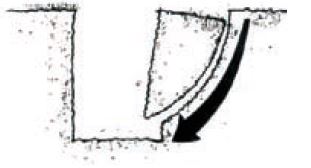
Rotation – common in clay-type soils when excavation walls are too steep, or when moisture content increases rapidly.
Soil is test:
A competent person must conduct visual and manual soil tests before anyone enters an excavation. Visual and manual tests are a critical part of determining the type of protective system that will be used.
Visual tests: Visual testing involves looking at the soil and the area around the excavation site for signs of instability. The competent person might do visual tests such as the following:
Observe the soil as it is excavated. Soil that remains in large clumps when excavated may be cohesive. Soil that breaks up easily is granular.
- Examine the particle sizes of excavated soil to determine how they hold together.
- Look for cracks or fissures in the faces of the excavation.
- Look for layers of different soil types and the angle of the layers in the face of the excavation that may indicate instability.
- Look for water seeping from the sides of the excavation.
- Look for signs of previously disturbed soil from other construction or excavation work.
- Consider vibration from construction activity or highway traffic that may affect the stability of the excavation.
Manual tests:
Manual testing involves evaluating a sample of soil from the excavation to determine qualities such as cohesiveness, granularity, and unconfined compressive strength. Soil can be tested either on site or off site but should be tested as soon as possible to preserve its natural moisture.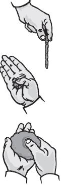
Plasticity test: Shape a sample of moist soil into a ball and try to roll it into threads about 1/8-inch indiameter. Cohesive soil will roll into 1/8-inch threads without crumbling.
Dry strength test: Hold a dry soil sample in your hand. If the soil is dry and crumbles on its own or with moderate pressure into individual grains or fine powder, it’s granular. If the soil breaks into clumps that are hard to break into smaller clumps, it may be clay combined with gravel, sand, or silt.
Thumb penetration test: This test roughly estimates the unconfined compressive strength of a sample. Press your thumb into the soil sample. If the sample resists hard pressure it may be type A soil. If it’s easy to penetrate, the sample may be type C.
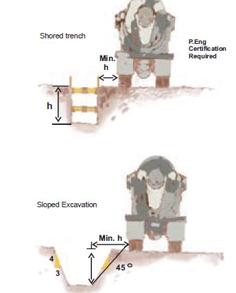
A support structure (shoring) is required, or the excavation walls must be sloped at an appropriate angle, before a worker enters an excavation considered to be:
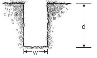
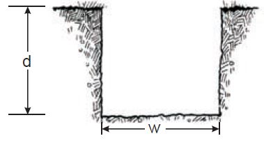
Trench (d>w) Excavation Open (w>d)Excavation
An openexcavation is any excavation that does not meet the criteria of being a trench, shaft, tunnel or caisson.
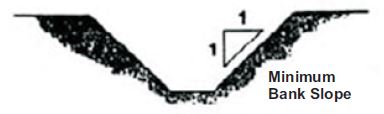
Sloped Excavations:
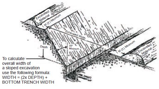
Fully sloped (Vee’d) excavations besides use of a shoring support structure, a safe method to protect workers in an excavation is to slope the walls of the excavations at a grade of 1H:1V (45 degrees) or flatter. The 45-degree slope is required no matter what type of soil conditions exist.
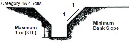
Combination slope and vertical face – A combination 1H:1V (45-degree) slope and vertical face may be used in some soils, as long as the vertical face does not exceed one metre (three feet), the overall depth of the excavation is not greater than five metres (16 feet), and where the soil is not subject to sloughing when saturated (ex: silt, sand, alluvial clay).
Shoring and shielding:
Shoring and shielding systems can prevent cave-ins in excavations with or without sloped / benched faces. The safest way to install and remove them is from outside the excavation.
The shoring (temporary support structure) must be designed to withstand allexternal forces that may be caused by: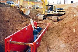
- soil pressures
- water pressures
- nearby structures
- additional loadings and vibrations (heavy equipment, traffic, temporary piled materials near the excavation, etc.)
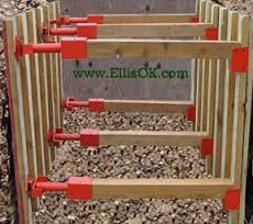
Shores are vertical or horizontal supports that prevent the faces of an excavation from collapsing. Vertical shores are called uprights. They’re easy to install, relatively inexpensive, and often used in stable soil or in shallow excavations that have parallel faces. Vertical shores must be sized for the excavation’s dimensions and soil type.
Horizontal shores are called walers. Walers are often used when unstable soil makes sloping or benching impractical and when sheeting is necessary to prevent soil from sliding into the excavation.
Shields provide employees a safe work area by protecting them from collapsing soil. Shields don’t prevent cave-ins but “shield” workers if a face does collapse. They are usually placed in the excavation by heavy equipment.
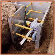
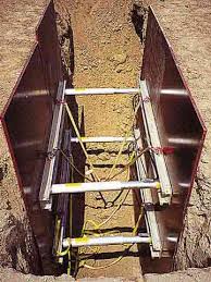
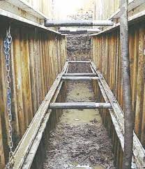
Installation of Shoring:
When installing shoring within a trench type excavation, appropriate procedures must be followed to provide for a safe excavation.
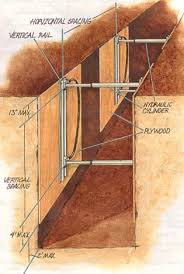
Uprights, struts (screw jacks), wales and plywood must be installed according to the shoring table that is based on the soil conditions, depth and width of the trench and excavation.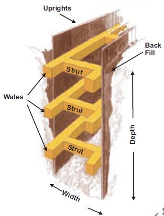
When installing shoring, the bucket of the excavation machine must be placed in the trench directly in front of the shoring being installed. The bucket will serve as additional protection if a cave-in occurs.
An appropriate ladder must be provided in a trench or open excavation. The ladder must extend at least one metre (three feet) above ground level at the surface of the excavation and be within three metres (10 feet) of a worker's working position inside the excavation.
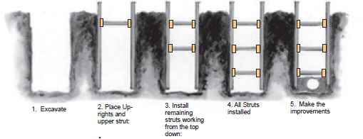
Shoring struts/jacks must be installed from the top down. It is important that the top (first) strut/jack is placed approximately 0.5 metres (18 inches) below the surface, and the second strut/jack is placed according to the shoring table. Installing the first and second strut/jacks is necessary to support the vertical uprights that stabilize the excavation walls.
When plywood is used as sheathing material, the jacks must be placed on the uprights that support the plywood. Jacks or struts must never be installed directly on to the plywood. If the walls move, the jack or strut could push through the plywood.
Once the worker has at least two struts/jacks placed on each set of uprights, the worker can proceed to install the bottom strut/jack. There must never be less than two struts/jacks used on each set of shoring.
This procedure must be followed with each set of shoring. This method protects the worker with the bucket of the digging machine and the shoring already
Shoring and shielding systems are available from manufacturers in a variety of dimensions, usually aluminum or steel, or they can be custom-built from tabulated data approved by a registered professionalengineer. Manufacturers will also provide tabulated data with their systems that includes engineering specifications, depth ratings, special instructions, and system limitations.
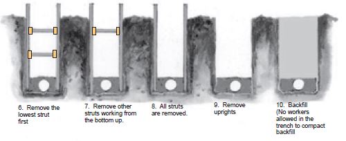
Shoring Removal: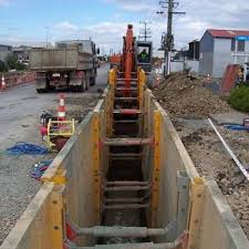
The procedure to remove shoring is the opposite of the procedure for installation. Struts are removed in the opposite order that they were installed. There must never be less than two sets of uprights in place. Workers removing the shoring must always stay between the shoring in place for protection.
Prior to removing a strut or jack, the trench should be back filled to a depth equal to the elevation of the strut or jack being removed. This back filling procedure shall be performed prior to removal of each strut or jack.
Sequence for the Installation and Removal of Shoring
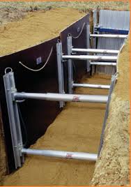
SHIELDS ( trench boxes ):
Shields, otherwise known as trench boxes, are generally used in open areas, but also may be
used in combination with battering and benching.
The excavated area between the outside of the trench box and the face of the trench should be as small as possible. The space between the trench box and the excavation side must be backfilled to prevent lateral movement of the box. Shields MUST not be subjected to loads exceeding those which the system was designed to withstand.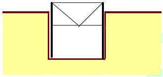
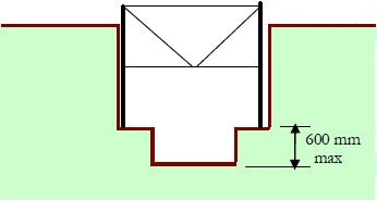
Shields can be used in the four different trenching situations indicated below:
(1) The shield rests on the excavation bottom and extends above the surface.
(2) The trench is narrowed and the shield is supported. When this method is used the shield must be tightly wedged into the trench.
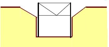
(3) The top of a shield in a slope battered trench shall be a minimum of 0.5 metres above the ground level.
(4) When an undersized shield is used, thetop of the trench SHALL be stabilised by battering. The maximum height of the battering SHALL be a maximum of 1.0 metre.
- Shields SHALL only be installed by a worker holding a current certificate of competency under the Lifts and Cranes Act.
- Heavy equipment SHALL always be used to place the box or shield in the trench.If there is sloping toward the
- excavation/trench, the trench box must extend at least 0.5 metres (18 inches) above the surrounding area. This can be done by providing a benched area adjacent to the box.
- Any modifications to the shields must be approved by the manufacturer.
- Workers SHALL only enter and leave the shield by using a ladder.
- Trench boxes may ride 0.6 metres (2 feet) above the bottom of an excavation, provided they are calculated to support the full depth of the excavation and there is no caving under or behind the shield.
- When shields are used as the only means of ensuring safety in the trench, workers SHALL NOT
(1) enter the excavation/trench before the shield has been installed
(2) work inside the trench, outside of the protection of the shield
(3) enter the excavation/trench after the shield has been removed
- Workers SHALL NOT remain in the shield while it is being moved.
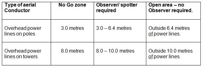
WORKING NEAR POWER LINES :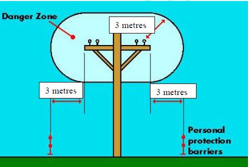
- The competent person SHALL check the work site and adjacent areas for the presence of aerial conductors.
- If aerial conductors are present and there is a possibility that the workers or plant will come within 10 metres of the conductors, the owner of the power supply/ electrical apparatus must be contacted to determine the nominal voltage.
- All conductors SHALL be considered to be alive and uninsulated.
- A trained safety observer SHALL be present and observing the work being carried out when there is a situation that any part of the plant being used for theexcavation/trenching work or load being delivered to the work site COULD enter the exclusion zone. eg 3 metres.
- The excavation equipment while the minimum clearances are maintained.
- If the excavation equipment is to be operated within the ‘no-go’ exclusion zone, work SHALL NOT commence until (1) the owner of the power supply/electrical apparatus is informed in writing of the nature and duration of the intended work and (2) written permission is received from the owner of the power supply/ electrical apparatus. A copy of these documents SHALL be kept on file.
- The workers must not allow any part of their body or any hand held tools within the ‘no-go’ exclusion zone.
Stability and adjacent structures:
Make sure that structures, roadways, and sidewalks adjacent to the excavation are adequately supported.
- Use an appropriate support system – such as shoring or bracing – if the excavation could affect the stability of nearby buildings, sidewalks, and roads.
- Don’t excavate below the base or footing of any foundation that might endanger employees unless you do one of the following:
- Use a support system that protects employees and keeps the structure stable.
- Ensure that the excavation is in stable rock.
- Have a registered professional engineer determine that the structure will not be affected by the excavation work.
- Have a registered professional engineer determine that the excavation work will not endanger employees.
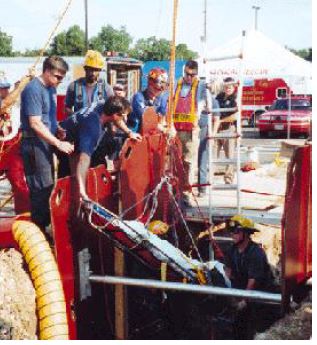
EXCAVATION / TRENCH RESCUE PROCEDURES:
While a person is in a trench, there SHALL be at least one other person at ground level.
This shall be adhered to at all times. In the event of a collapse, the worker on top may have some idea where the trapped worker could be located.
In the event of a collapse the following procedure should be adopted.
- Send someone immediately to telephone or radio for emergency services that may be needed. Ensure that the person sent to make the call is relatively calm, can communicate clearly and knows where the telephone is.
- Look for evidence of where the trapped person is eg. tools, safety helmet etc.
- Try to locate what section of the collapsed excavation/trench the person is trapped in.
- Clear the area of all non-required personnel.
- Identify if any further collapse is likely.
- Establish and arrange for a person to monitor a safety zone.
- If possible, batter the sides of them excavation/trench in the collapsed area.
- Install shoring where possible to protect the trapped person and the rescuers.
- Carefully remove the collapsed soil with shovels. NEVER have anyone on top of the collapsed soil. They may be on top of the person trapped beneath the soil.
- If the excavation/trench is over 1.5 metres deep, rescuers SHALL wear safety harnesses with lifelines attached securing them to the surface.
- If the excavation/trench is over 1.5 metres deep, rescuers SHALL wear safety harnesses with lifelines attached securing them to the surface.
- When the digging is close to the trapped person, continue excavation using hands. If shovels have to be used, extreme care must be taken not to cause any further injury to the person who is trapped.
- When the trapped person has been located, clear soil from around the head and chest areas. Check for breathing and a pulse.
- If breathing has stopped – commence expired air resuscitation (E.A.R.) and continue until emergency services have arrived and have taken over.
- If breathing has stopped and no pulse is present, commence E.A.R. and C.P.R. and continue until emergency services have arrived and have taken over.
- After the trapped person has been freed, treated and stabilized by the emergency services personnel, make arrangements for the person to be removed from the excavation/trench in a safe manner, ensuring that no further collapse occurs during this operation.
After the trapped person has been removed from the collapsed excavation/ trench:
- Follow ACC accident reporting procedures, taking into account all related legal requirements. Notify the Corporation’s OH&S Representative immediately.
- Take the appropriate actions to preserve the accident scene.
- Take photographs of the accident scene.
- Using blue or black ink, fill in accident report documentation.
- Put on file a hard copy of:
1. all excavation/trench daily check lists that were filled in on the day of the accident,
2. confined space entry permits for the day of the accident,
3. the accident report,
4. photographs of the accident scene,
5. any other documentation related to the accident
Click the below link to download the documents for excavation safety

WORK PERMITS
Excavation permit-1 Excavation permit-2 Excavation permit-3 Excavation permit-4
Excavation permit-5 Excavation permit-6 Excavation permit-7 Excavation permit-8
Excavation permit-9 Excavation permit-10
Safety Check sheet - Excavation