Definition:
Ventilation is the mechanical system in a building that brings in "fresh" outdoor air and removes the "contaminated" indoor air.
In a workplace, ventilation is used to control exposure to airborne contaminants. It is commonly used to remove contaminants such as fumes, dusts, and vapours, in order to provide a healthy and safe working environment. Ventilation can be accomplished by natural means (e.g., opening a window) or mechanical means (e.g., fans or blowers).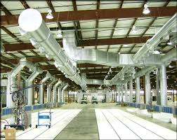
Industrial systems are designed to move a specific amount of air at a specific speed (velocity), which results in the removal (or "exhaust") of undesirable contaminants. While all ventilation systems follow the same basic principles, each system is designed specifically to match to the type of work and the rate of contaminant release at that workplace.
Purpose of a ventilation system:
There are four purposes of ventilation:
- Provide a continuous supply of fresh outside air.
- Maintain temperature and humidity at comfortable levels.
- Reduce potential fire or explosion hazards.
- Remove or dilute airborne contaminants.
Why have an industrial ventilation system:
Ventilation is considered an "engineering control" to remove or control contaminants released in indoor work environments. It is one of the preferred ways to control employee exposure to air contaminants.
Other ways to control contaminants include:
- eliminate the use of the hazardous chemical or material,
- substitute with less toxic chemicals,
- process change, or
- work practice change.
Parts of an industrial ventilation system:
Systems are composed of many parts including:
- an "air intake" area such as a hood or an enclosure,
- ducts to move air from one area to another,
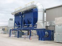
- air cleaning device(s), and
- fan(s) to bring in outside air and exhaust the indoor contaminated air.
Each of these parts are discussed in this series of documents.
Basic types of ventilation systems:
There are two types of mechanical ventilation systems used in industrial settings:
Dilution (or general) ventilation reduces the concentration of the contaminant by mixing the contaminated air with clean, uncontaminated air.
Local exhaust ventilation captures contaminates at or very near the source and exhausts them outside.
Main features of dilution ventilation:
Dilution, or "general", ventilation supplies and exhausts large amounts of air to and from an area or building. It usually involves large exhaust fans placed in the walls or roof of a room or building.
Dilution ventilation controls pollutants generated at a work site by ventilating the entire workplace. The use of general ventilation distributes pollutants, to some degree, throughout the entire work site and could therefore affect persons who are far from the source of contamination.
Dilution ventilation can be made more effective if the exhaust fan is located close to exposed workers and the makeup air is located behind the worker so that contaminated air is drawn away from the worker's breathing zone. See Figure 1 for examples of good and poor dilution ventilation design.
When used to control chemical pollutants, dilution must be limited to only situations where:
- the amounts of pollutants generated are not very high,
- their toxicity is relatively moderate, and
- workers do not carry out their tasks in the immediate vicinity of the source of contamination.
It is therefore unusual to recommend the use of general ventilation for the control of chemical substances except in the case of solvents which have admissible concentrations of more than 100 parts per million.
Figure 1
Figure 2
Figure 3
Figure 4
Figures 1 to 4: Examples of recommended dilution ventilation
Figure 5
Example of not recommended dilution ventilation
Components of local exhaust ventilation:
A local exhaust system has six basic elements (see Figure 6):
- A "hood" or opening that captures the contaminant at the source.
- Ducts that transport the airborne chemicals through the system.
- An air cleaning device that removes the contaminant from the moving air in the system (not always required).
- Fans that move the air through the system and discharges the exhaust air outdoors.
- An exhaust stack through which the contaminated air is discharged.
- Make up air that replaces the exhausted air.
Figure 6
Basic components of a local exhaust system
Which type of ventilation system is best for my workplace:
All industrial ventilation systems, when designed properly, should be able to provide long-term worker protection. The two types of ventilation, dilution and local exhaust, are compared in the following table.
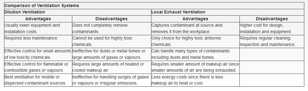
limitations of any ventilation system:
Some limitations include:
- The systems deteriorate over the years because of to contaminant build-up within the system, especially filters.
- Require ongoing maintenance.
- Regular and routine testing is needed to identify problems early and implement corrective measures.
- Only qualified persons should make modifications to a ventilation system to make sure the system continues to work effectively.
The following is an example of changes that can affect how a system works:
Figure 7
Adding a duct branch
A hood and branch are added to an existing duct. The local exhaust ventilation pulls air into the system from the new location, which will reduce the airflow from other locations that are further away from the exhaust fan. Again, airflow will all be affected. The result is that the system will plug more rapidly and the air flows at the other hoods may not be adequate enough to remove contaminants.
Measures for dilution ventilation rates:
Air Changes per minute (ACM) [or air changes per hour (ACH)] is generally used as a way to measure the dilution ventilation rate. Air exchange rate means replacing the entire volume of air in the work space in one minute or one hour. The following formula can be used to determine the air exchange rate:
For example if the air flow rate required in a work space which is 40 feet long, 40 feet wide and 12 feet high, volume of the work space is 40 x 40 x 12 = 19,200 cubic feet.
Air flow rate required per ACH = 19,200 / 60 = 320 cfm
Or, air flow rate required per ACM = 19,200 cfm
Or, if the ceiling height is 20 feet high then the room volume is 40 feet X 40 feet X 20 feet high= 32,000 cubic feet and the required air flow rate will be as follows:
Air flow rate required per ACH = 32,000 / 60 = 533 cfm
Or, air flow rate required per ACM = 32,000 cfm
The required air change rate is sometimes given in ventilation regulations and ventilation design standards. For example, a flammable storage room requires six air changes per hour according to US OSHA requirements. The Canadian National Building Code (NBC) requires residential houses to mechanical ventilation system capable of providing at least one half (0.5) air changes per hour during the heating season to avoid chimney back drafting.
However, air changes per hour (or minute) may not be an appropriate measure for ventilation criteria when controlling certain hazards, heat and/or odors. Ventilation should be determined on the amount of contaminant generated, and the toxicity of that contaminant (not just the size of the room).
Design standards available:
Although there are not many specific government codes and regulations, there are many recommended standards. The important ones are described below (in no particular order):
Please see the OSH Answers document Industrial Ventilation - Glossary of Common Terms for a description of the acronyms.
Ontario Occupational Health and Safety Act - Regulation 851 for Industrial Establishments (section 127 & 128) mentions general requirements for adequate ventilation and replacement air.
British Columbia O.H.& S Regulation - BC Regulation 296/297 Part 5.60-5.71 gives the detailed requirements for dilution ventilation, LEV, make-up air, discharged air and re circulation of discharged air.
OSHA - This US Government agency has promulgated a few ventilation standards, e.g., the four standards in 29CFR1910.94 dealing with local exhaust systems. OSHA's construction standards in 29CFR1926 contain ventilation standards for welding. Such ventilation systems are "required," but OSHA usually does not consider its ventilation standards violated unless exposure standards are also violated.
NIOSH - This US Government research organization has published a number of useful ventilation documents, including publications on foundry ventilation, re circulation, and push - pull hoods.
AMCA - This US trade association has developed standards and testing procedures for fans. It has a number of useful publications related to fan selection, testing, troubleshooting and certification (e.g., AMCA 201).
ASHRAE - This US based society of heating and air conditioning engineers has produced a number of standards related to indoor air quality (IAQ), filter performance and testing comfort, and HVAC systems.
ANSI -This US based consensus standards setting organization has produced several important standards on ventilation including paint spray booths, grinding exhaust hoods, open sun tank exhausts and laboratory ventilation.
ACGIH - The ACGIH Industrial Ventilation Committee publishes the manual of recommended practice for industrial ventilation. The Manual has been recognized worldwide a useful source of information on all aspects of IVS.
SMACNA - This US association of sheet metal contractors and suppliers sets standards for ducts and duct installation.
NFPA - This US based fire protection association has produced a number of recommendations (which become requirements when adopted by local fire agencies), e.g. NFPA 45 lists a number of ventilation requirements for Lab Fume hood use.
BUILDING CODES - There are building codes set or adopted by almost every city, county and municipality. All industrial buildings have to be built to these codes in order to have a building accepted. However, most have little direct reference to industrial ventilation, but these codes need to be checked.
Duct system:
The ventilation system in a building consists of air moving devices such as fans and blowers and a network of ducts to exhaust the contaminated indoor air and to bring in air from the outside of the building.
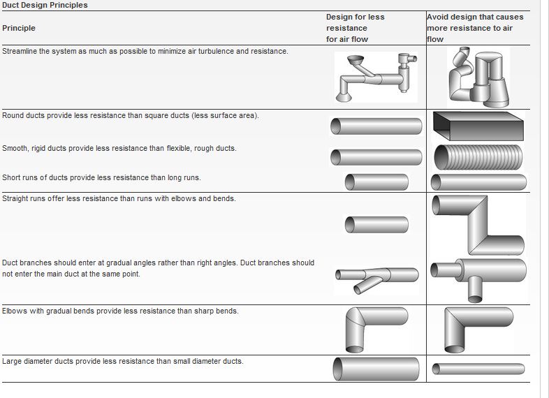
Basic principles of duct design:
Duct systems should be designed to have air flow through the ducts with as little friction or resistance as possible. The amount of air that flows through a duct depends on the cross section area (duct opening area) of the duct and the air speed. Air moving too slowly will allow contaminants such as dusts to settle and accumulate and these particles will eventually clog the duct. Air moving too fast wastes power, can create noise problems, and may cause excessive abrasion by dust particles hitting the ducts. Recommended speed ("duct velocity") for different types of contaminants can be found in reference books on ventilation.
Duct systems typically require large amounts of air to move relatively small amounts of contaminants. The required volume of airflow depends of the acceptable concentration of air contaminants in the inside work space. A carefully designed system can achieve the required air concentration while using the least amount of power. Other design considerations include initial capital costs, reliability, maintenance, and durability of air handling equipment.
The table below illustrates some basic duct design principles.
Causes of leakage or plugging to a duct:
Ducts can plug or leak for the following main reasons:
Low air speed: Inside the ducts, air speed must be in a range that is adequate to move contaminant effectively. Changing the duct size or the airflow through any duct can change the minimum speed. One small change in one section of the system can affect the overall system and its performance.
Flexible ducts: Corrugated flexible ducts create more friction and bend losses that slow down air movement.
Modifications of the duct system: If hoods and ducts are added to the existing duct system, it is necessary to adjust or "re balance" the airflow. If not properly re balanced, the system will "self-balance" - typically the airflow will be reduced in the sections that have higher resistance. Reduced airflow will cause particulates to settle out of the air stream and the ducts to plug.
Particulate traps, settling chambers, or "clean outs" are not present or used: Frequent cleaning of specific points in the duct network (those that plug first) can reduce the need for a major system cleaning. By monitoring the most common trouble spots, the effort needed to maintain the ducts is minimized. At locations of rapid or frequent plugging, clean out or access doors make cleaning much easier. See Figure 1.
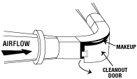
Figure 1
Typical Clean out Door for Duct Network
Airflow changes direction abruptly: Deposits are more common in short radius elbows and "T" type branch connections. The figures below shows the examples of abrupt air direction changes.

Figure 2(a)
Short radius elbows create heavy deposits
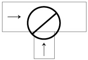
Figure 2(b)
Never use "T" Connection
Figure 2(a) & 2(b)
Abrupt Air Direction Changes
What are fans:
Fans are the "workhorses" of the ventilation systems. In order to have an effective ventilation system, fans must be the appropriate size and type. They must provide enough speed (air movement) to capture contaminants at the source, draw them through the hood, and carry them through the duct system, through the air cleaning devices and exhaust to the outdoors.
Types of fans are available:
There are two main types of exhaust fans:
- Axial Fans: These fans look like propellers and draw air straight through the fan.
- Centrifugal fans: These fans look like "squirrel cages" that draw air into the centre of the fan and exhaust it at a 90-degree angle.
Axial or propeller fans:
There are three basic types of axial fans: propeller, tubeaxial, and vaneaxial. Propeller fans are most commonly used for dilution ventilation or cooling. These fans are often mounted in a wall or ceiling. Common examples are your automobile radiator fan or a free standing room fans. The basic characteristics of these fans include that they:
- can move large amounts of air if there is little resistance,
- are not suited for local exhaust ventilation because they do not provide enough suction to draw air through the system.
Tubeaxial and vaneaxial fans are essentially propeller fans made to fit in a duct. They are usually limited to "clean air" applications such as exhaust ducts going through the roof.
Centrifugal fans:
There are three types of centrifugal fans determined by the type of fan blades:
- forward inclined blades,
- backward inclined blades, and
- straight radial blades.
The fans in your home furnace, vacuum cleaner and hair dryer are examples of centrifugal fans. They can operate against a high resistance and are typically used in local exhaust ventilation systems. The rugged radial blade centrifugal fans are the best type for exhausting heavy amounts of dust because they are less likely to become clogged or abraded by the dust.

Figure 1
Types of fans
How do you know if the correct type of fan has been selected:
Selection of the proper fan can be complicated and should be done by a ventilation or fan expert. However, you can make the following observations to determine if the fan selected is appropriate:
Material handled through the fan
- If the exhaust air contains a small amount of smoke or dust, a backward inclined centrifugal or axial fan should be selected.
- If the exhaust air contains light dust, fume or moisture, a backward inclined or radial centrifugal fan would be preferred.
- If the particulate load in the exhaust air is high or when material is handled, the normal selection would be a radial centrifugal fan.
- If the exhaust air contains explosive or flammable material, spark resistant construction (explosion proof motor if the motor is in the air stream) should be selected to conform to the standards of the National Fire Protection Association and provincial governmental regulations.
- If the exhaust air contains corrosive contaminants, a protective coating or special materials of construction (stainless, fibreglass, etc.) may have to be used in construction of the fan and motor.
Capacity:
You may or may not know how much air has to be moved by the fan. You may also not know the amount of resistance in the exhaust system that the fan has to overcome and what is the fan efficiency. However, the following general information may be helpful:
- Fan size should be determined by performance requirements. Inlet size and location, fan weight and ease of maintenance also must be considered. The most efficient fan size may not fit the physical space available.
- On packaged fans, the motor is furnished and mounted by the manufacturer (direct-drive). On larger units, the motor is mounted separately and coupled directly to the fan or indirectly by a belt drive.
- Direct Drive fans offer a more compact assembly and assure constant fan speed. Fan speeds are limited to available motor speeds. Capacity is set during construction.
- Belt Drive fans offers flexibility in that fan speed, which can be changed by altering the drive ratio. This flexibility may be important in some applications to provide for changes in system capacity or pressure requirements due to changes in process, hood design, equipment location or air cleaning equipment.
- It is normally a custom to select a fan that is working at no more than 80% of its full rated speed. The motor selected should be able to handle the horsepower required to achieve that speed i.e. a speed increase of 20%.
Safety:
Safety guards are required for all danger points such as inlet, outlet, shaft, drive and cleanout doors. Construction should comply with applicable provincial governmental safety requirements.
What is a hood:
A hood - correctly called a local exhaust hood - is the point where contaminated air is drawn into the ventilation system. The sizes and shapes of hoods are designed for specific tasks or situations. The air speed (velocity) at the hood opening and inside the hood must be enough to catch or capture and carry the air contaminants. To be most effective, the hood should surround or enclose the source of contaminant or be placed as close to the source as possible.
What are the common types of hood:
The three common classes of hoods are:
- Enclosing.
- Receiving.
- Capturing.
Enclosing Hood:
Enclosing hoods, or "fume" hoods, are hoods surrounding the process or point where the contaminants are generated. Examples of completely enclosed hoods (all sides enclosed) are glove boxes and grinder hoods. Examples of partially enclosed (two or three sides enclosed) hoods are laboratory hoods or paint spray booths. The enclosing hood is preferred whenever possible.
Figure 1
Partially Enclosed Hood
Receiving Hood:
These hoods are designed to "receive" or catch the emissions from a source that has some initial velocity or movement. For example, a type of receiving hood called a canopy hood receives hot rising air and gases as shown in Figure 2. An example is a canopy hood located over a melting furnace.
Figure 2
Receiving Hood
Capturing Hood:
These hoods are located next to an emission source without surrounding (enclosing) it. Examples are a rectangular hood along the edge of a tank (as shown in Figure 3) or a hood on a welding or grinding bench table (figure 4) or a downdraft hood for hand grinding bench (figure 5).
Figure 3
Capturing Hood
Figure 4
Capturing hood for welding or grinding bench
Figure 5
Downdraft Hood for hand grinding
"capture velocity"?
The ventilation system removes contaminants by "pulling" the air (and the contaminant) into the exhaust hood and away from the worker or the source. Airflow toward the hood opening must be fast or high enough to "catch and transport" the contaminant until it reaches the hood and ducts. The required air speed is called the "capture velocity".
Any air motion outside of the hood and surrounding area may affect how the air flows into the hood. The ventilation system will require a higher airflow speed to overcome air disturbances. As much as possible, the other sources of air motion should be minimized or eliminated for the ventilation system to work effectively.
Common sources of external air movement include:
- Thermal air currents, especially from hot processes or heat-generating operations.
- Motion of machinery such as by a grinding wheel, belt conveyor, etc.
- Material motion such as dumping or filling.
- Movements of the operator.
- Room air currents (which are usually taken at 50 fpm (feet per minute) minimum and may be much higher).
- Rapid air movement caused by spot cooling and heating equipment.
Most of the capture velocities are around 100 feet per minute (fpm). How fast is 100 fpm? Blowing lightly on your hand so that you can just barely feel air movement is about 100 fpm. It is easy to see how it will take very little air movement from other sources to affect how well a hood can capture contaminants. (See Figure 6).
Figure 6
Competitors to Capture Velocity
General rules for hood design?
The shape of the hood and its size, location, and rate of airflow each play an important role in design considerations. Each type of hood also has specific design requirements, but several general principles apply to all hoods:
- The hood should be placed as close as possible to the source of contamination, preferably enclosing it. The more completely enclosed the source is, the less air will be required for control. The required volume varies with the square of the distance from the source as shown in Figure 7.
- The air should travel from source of the contaminant and into the hood with enough velocity (speed) to adequately capture the contaminant.
- The hood should be located in a way that the operator is never between the contaminant source and the hood.
- The natural movement of contaminants should be taken into consideration. For example, a hood should be placed above hot processes to trap rising gases and heat. A grinding wheel or woodworking machine should be equipped with a partial enclosure to trap the flying particles where they spin off.
- The flanges or baffles should be used around the hood opening to increase the capture effectiveness and reduce ventilation air requirements.
Figure 7
If a hood moved from two inches away from a source to four inches away (twice the distance), the required airflow will be four times greater to provide the same degree of capture.