What is wire rope?
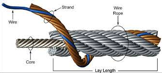
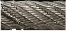
By definition, wire rope is a twisted bundle of drawn steel wires. It is usually composed of wires, strands and a core. The wires are drawn to a pre-determined size and laid together in various arrangements having a definite pitch (or lay) to form a strand. The required number of strands are helically laid or formed around the core, which may be a core of synthetic or natural fiber, a metallic strand or an independent wire rope core.
The size, number and arrangement of wires, the number of strands, the lay and the type of core in a rope are determined largely by the service for which the rope is to be used. Flexibility and abrasion are the most important considerations; other factors, such as load conditions, rope speeds, vibration, crushing, and equipment design also must be considered.
Wire rope classification:
Wires are the basic building blocks of a wire rope. They lay around a “center” in a specified pattern in one or more layers to form a strand. The strands are helically laid together around a center, typically some type of core, to form a wire rope.
The strands provide all the tensile strength of a fiber core rope and over 90% of the strength of a typical 6-strand wire rope with an independent wire rope core.
Properties like fatigue resistance and resistance to abrasion are directly affected by the design of strands.


Wire ropes cores:
Wire rope consists of multi strand metal wires wrapped around a suitable core material. Wire-rope cores are carefully designed and must be precisely manufactured to close tolerances to ensure a perfect fit in the rope. The most common types of cores include the following
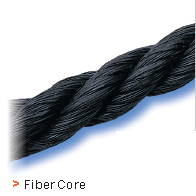
1. FIBER CORE (FC)Polypropylene is standard, but either natural sisal (or hemp) fiber or other man-made fibers are available on special request.
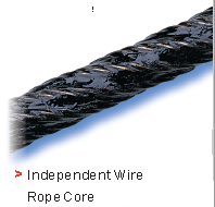
2. INDEPENDENT WIRE ROPE CORE( IWRC): Literally an independent wire rope with strands and a core, called IWRC. Most wire ropes made with steel core use an IWRC. The primary function of the core is to provide adequate support for the strands. As the name implies, an IWRC is a separate small-diameter wire rope that is used as the core for a larger wire rope. When severe crushing or flattening of the rope is encountered, an IWRC is usually specified.
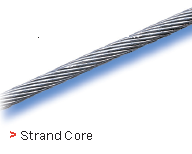
3. STRAND CORE A strand made of wires. Typically, strand cores are used in utility cables only. This type of core has a single strand used as the core. This type is generally confined to the smaller ropes as a substitute for IWRC. The strand core may or may not have the same cross section as the surrounding strands.
Wire ropes lays:
The first two meanings of “lay” are descriptive of the wire and strand positions in the rope. The
third meaning is a length measurement used in manufacturing and inspection.
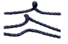
1. The direction strands lay in the rope – right or left. When you look down a rope, strands of a right lay rope go away from you to the right. Left lay is the opposite. (It doesn’t matter which direction you look.)
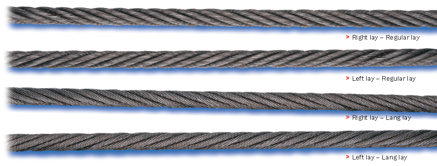
2. The relationship between the direction strands lay in the rope and the direction wires lay in the strands. In appearance, wires in regular lay appear to run straight down the length of the rope, and in Lang lay, they appear to angle across the rope. In regular lay, wires are laid in the strand opposite the direction the strands lay in the rope. In Lang lay, the wires are laid the same direction in the strand as the strands lay in the rope.
3. The length along the rope that a strand makes one complete spiral around the rope core. This is a measurement frequently used in wire rope inspection. Standards and regulations require removal when a certain number of broken wires per rope lay are found.
Standard Rope Classification:
All rope of the same size, grade and core in each classification have the same minimum breaking force and weight per foot. Different constructions within each classification differ in working properties. Consider these features whenever you’re selecting a rope for a specific application.
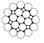
The 6 x 19 classification of wire ropes includes standard 6 strand, round strand ropes with 16 through 26 wires per strand. The 6 x 36 classification of wire ropes includes standard 6 strand, round strand ropes with 27 through 49 wires per strand. Although their operating properties vary, all have the same weight per foot and the same minimum breaking force, size for size.
While the 6 x 19 ropes give primary emphasis to abrasion resistance in varying degrees, the 6 x 36 ropes are important for their fatigue resistance. This fatigue resistance is made possible by the greater number of small wires per strand.
Although there are exceptions for special applications, the constructions in 6 x 36 classification are primarily designed to be the most efficient for each rope diameter. As the rope size increases, for instance, a large number of wires can be used to achieve required fatigue resistance, and still those wires will be large enough to offer adequate
resistance to abrasion.
Properties of standard 6 X 19 and 6 X 36 wire ropes:


Determination of wire rope diameter:
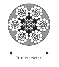
The actual diameter of a wire rope is the diameter of a circumscribed circle that will enclose all the strands. It’s the largest cross-sectional measurement as shown here. You should make the measurement carefully with calipers.
The rope diameter should be measured on receipt for conformity with the specification. British Standard (B.S. 302:1987, standard steel wire rope, Part 1. Clause 5.1) allow for a tolerance of - 1% to 4 % of the nominal rope diameter.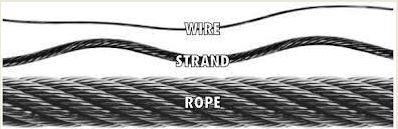
The generally accepted method of measuring rope diameter for compliance with the standard is to use a caliper with jaws broad enough to cover not less than two adjacent stands. The measurement must be taken on a straight portion of rope at two points at least 1 meter apart. At each point two diameters at right angles should be measured. The average of the four measurement is the actual diameter.
After the rope has made the first few cycles under low load, the rope diameter should be measured at several points. The average value of all the measurements at each point must be recorded and will form the basis of comparison for all future measurements.
The measurements of the rope diameter an essential part of all inspections and examinations. It ensures the maximum diameter reduction does not exceed the recommended figure. As stated in 5.2 British standard 6570 recommends that a wire rope should be discarded when the diameter of the rope is reduced to 90% of the nominal diameter.
A comparison of the measured data with the recorded previous values can detect an abnormal rate of reduction in diameter. Coupled with assessment of previous rope examination data, the probable date of rope renewal can be predicted.
If we examine the cross-section of a six-stand wire rope, we will find that measuring the thickness of the rope over the crowns (Fig-a) will produce a higher value than measuring it over the valleys (Fig-b). The actual diameter of the rope is defined as the diameter of the circumscribing circle.
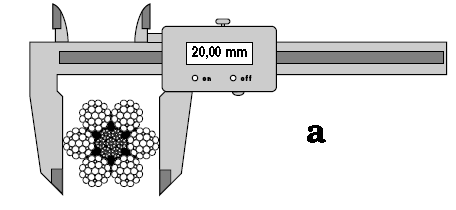
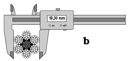
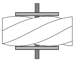
When using a conventional caliper, wire rope with an even number of outer strands (four-, six, eight-, and multi strand) ropes must be measured from crown to crown. The advantage of a proper wire rope caliper with measuring plates is that even if the measurement is carried out "incorrectly", adjacent crowns are always included, so that the actual diameter is determined at any section. (Fig-c)
Measuring the diameter of wire rope with an uneven number of outer strands (three, five, seven, or nine-strand ropes) is more complicated: a crown on the one side of the wire rope always has a valley as a counterpart on the other side of the wire rope. A conventional caliper, therefore, has to be applied diagonally to the axis of the rope, so that at any time a crown adjacent to a valley is covered. Again a wire rope caliper with measuring plate is definitely to be preferred as it always includes strands crowns.
In all cases during periodic examinations where the measurements are to be recorded, the rope should be measured as already described. Where the roundness is being checked to detect potential faults, two diameters, one at right angles to the other can be taken and noted in the records. The entry into the records might read rope diameter : 20.4/20.5mm.
Measuring rope lay:
After a rope has been fitted to the appliance, its length cannot be measured again accurately, with out a great deal of trouble. The purpose of measuring the length of lay is to detect any increase in the rope length which may have been caused by corrosion, core deterioration or rope rotation (unlaying). With n new rope the wire and strands should be allowed to settle into their permanent position. Six or seven lifting cycles with a light to medium load are recommended before measuring error, the measurement should be made over four lays and the length divided by four lays and the length divided by four to find the average lay length.
On eight strand ropes the eight, sixteen, twenty-four and thirty-second strands must be marked. Using a straight length of the rope and with the rope under no load, first mark any strand on the crown with a piece of chalk; this strand now become'' crown zero''. Excluding this strands, count the next eight strands and mark the eight strand with chalk. Exclude the eight strand and repeat the procedures further two times. The measured length between the outer chalk marks is then divided by four to give the lay length.
As a rough check on the overall accuracy of the chalk marking, the length of lay for eight strand ropes is approximately between 6.25 and 6.5 x the diameter of the rope e.g. using a lay length of 6.5 x rope diameter, four lay length of a 32mm diameter rope will be 32mm x 6.5 x 4=832mm.
An alternate method of measuring the rope lay is to secure the free end of the roll of adding machine paper to the rope with adhesive tape. The paper is rolled out over the rope and simultaneously the wax pencil is drawn over the paper, providing a clear print of the outer wires of the rope. The finished print can be field for comparison with later measurements.
A third method is to wrap typing carbon papers round the rope under the roll of paper. By rubbing along the paper with a piece of cardboard, the carbon marking on the underside of the paper can be confined to the tops of the strand crowns.


Wire rope wear, abuse – and removal criteria:
A hoist wire rope is a machine in and of itself that requires proper selection, installation, and maintenance. As a wire rope is used in a hoisting application, the individual wires move and allow the rope to bend around the drum and sheaves. This movement causes friction and abrasive forces that require proper lubrication. If selection, installation, operation, or maintenance is improper, the rope life will be shortened dramatically. Even under the optimum conditions and usage, every wire rope used in a hoisting application will eventually fail. Therefore, routine periodic inspections, by a trained and qualified inspector must be employed to determine the condition of the wire rope so that replacement made before the rope fails.
When we look at wire rope wear and failure, there are numerous possible causes. Possible causes include:
- Abrasion Caused Failure
- Core Protrusion
- Corrosion Caused Failure
- Cut or Shear Caused Failure
- Fatigue Caused Failure
- Tension Caused Failure (Overloading of Rope)
Abrasion Breaks (Externally Induced Damage)
Abrasion wire breaks of hoist wire ropes are located at points where the rope has been damaged by improper contact with hoist sheaves and drums or has struck an external object such as the crane girder or shelving. Improperly grooved sheaves and drums or improper fleet angle into the sheaves can often cause this kind of damage. Wire breaks caused by abrasion show broken wire ends worn to knife-edge thinness.
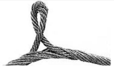
Core Slippage or Protrusion (Shock Load or Improper Installation)
Core protrusion can be caused by shock loading as well as improper installation. Rotation-Resistant wire ropes on hoists must be installed with extra care and proper handling to prevent rope damage during installation. The lay length of a rotation-resistant rope must not be disturbed during the various stages of installation. By introducing twist or torque into the rope, core slippage may occur—the outer strands become shorter in length, the core slips and protrudes from the rope. In this condition, the outer strands become overloaded because the core is no longer taking its designed share of the load. Conversely, when torque is removed from a rotation-resistant rope core slippage can also occur. The outer strands become longer, and the inner layers or core become overloaded, reducing service life and causing rope failure.
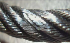
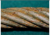
Corrosion Breaks (Poor Lubrication)
Wire ropes that fail due to corrosion are usually indicative of improper lubrication. Corrosion is easily identified by the pitted surface on individual wires of the rope. Broken wires do not usually show evidence of tension, abrasion, and fatigue. The extent of the damage to the interior of the rope is extremely difficult to determine; consequently, corrosion is one of the most dangerous causes of rope deterioration.
Cut or Shear (Externally Induced Damage)
In this type of wire rope damage, the wire will be pinched down and cut at broken ends or will show evidence of a shear-like cut. This condition is evidence of mechanical damage cause from an external source or wear or damage on equipment components such as a broken flange on a sheave or sharp drum grooves.
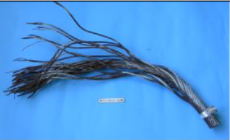
Fatigue Breaks (Repetitive Bending Wear)
Hoist wire ropes are subject to a lot of repetitive bending over sheaves, which causes the wire to develop cracks in its individual wires. These broken wires often develop in the sections that repetitively move over sheaves. The smaller the sheave is in relationship to the diameter of the wire rope, the higher the bending fatigue. This process will become escalated as a rope travels on and off of a grooved single layer drum, which also causes a bending cycle.
Fatigue breaks often develop in segments as stated before these segments are usually the part of the rope surface that comes into direct contact with a sheave or drum. Because this is caused by external elements rubbing, often these breakages are external and visible for the eye to see. Once broken wires start to appear, it creates a domino effect and quickly much more will appear. Square ends of wires are common for fatigue breaks. These breaks are considered a long term condition and are to be considered part of the normal to the operating process.
Tension Failure (Overload / Shock Loading)
Tension failure is caused by overloading of the wire rope. The overloading can be based upon the original strength of a new wire rope or for the remaining strength of a used wire rope. When a wire rope has failed due to excessive tension, the broken rope will show one end of broken wire coned and the other cupped. Necking down of the broken ends is typical of this type of break. Tension breaks are often caused due to shock loading a slack rope that induces excessive impact stress on the rope.
REMOVAL CRITERIA:
A major portion of any wire rope inspection is the detection of broken wires. The number and type of broken wires are an indication of the rope’s general condition and a benchmark for its replacement.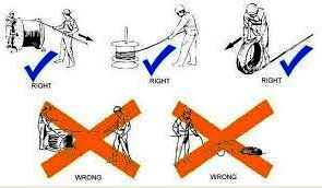
Frequent inspections and written records help determine the rate at which wires are breaking. Replace the rope when the values given in the table below are reached. Valley wire breaks – where the wire fractures between strands or a broken wire protrudes between strands – are treated differently than those that occur on the outer surface of the rope.
When there is more than one valley break, replace the rope. Broken wire removal criteria cited in many standards and specifications, like those listed below, apply to wire ropes operating on steel sheaves and drums. For wire ropes operating on sheaves and drums made with material other than steel, please contact the sheave, drum or equipment manufacturer or a qualified person for proper broken wire removal criteria.
Wire rope inspection:
All wire ropes will wear out eventually and gradually lose work capability throughout their service life. That’s why periodic inspections are critical. Applicable industry standards such as ASME B30.2 for overhead and gantry cranes or federal regulations such as OSHA refer to specific inspection criteria for varied applications.
THREE PURPOSES FOR INSPECTION
Regular inspection of wire rope and equipment should be performed for three good reasons:
- It reveals the rope’s condition and indicates the need for replacement.
- It can indicate if you’re using the most suitable type of rope.
- It makes possible the discovery and correction of faults in equipment or operation that can cause costly accelerated rope wear.
HOW OFTEN
All wire ropes should be thoroughly inspected at regular intervals. The longer it has been in service or the more severe the service, the more thoroughly and frequently it should be inspected. Be sure to maintain records of each inspection.
APPOINT A QUALIFIED PERSON TO INSPECT
Inspections should be carried out by a person who has learned through special training or practical experience what to look for and who knows how to judge the importance of any abnormal conditions they may discover. It is the inspector’s responsibility to obtain and follow the proper inspection criteria for each application inspected.
How to extend rope service life:
How long will your rope last? There is not a simple answer but, rather, there are several factors involved, including:
- The manner in which you install and “break in” your new rope.
- The operating technique and work habits of the machine operators.
- Physical maintenance of the rope throughout its service life.
- Physical maintenance of the system in which your rope operates.
INSTALL YOUR ROPE CORRECTLY
The primary concern when installing a new rope is to not trap any twist in the rope system. Proper handling of the rope from the reel or coil to your equipment will help avoid this situation. Another important step on smooth faced drums is to spool with tensioned wraps tight and close together on the first layer. This layer forms the foundation for succeeding layers. Finally, spool the remaining rope on the drum with tension approximating 1% to 2% of the rope’s minimum breaking force.
BREAK IN YOUR NEW ROPE PROPERLY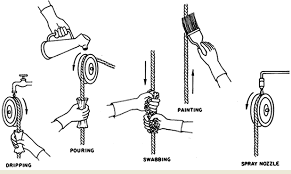
When you install a new operating rope, you should first run it for a brief period of time with no load. Then, for best results, run it under controlled loads and speeds to enable the wires and strands in the rope to adjust to themselves.
“CONSTRUCTIONAL” STRETCH
When first put into service, new ropes normally elongate while strands go through a process of seating with one another and with the rope core. This is called “constructional” stretch because it is inherent in the construction of the rope, and the amount of elongation may vary from one rope to another. For standard ropes, this stretch will be about 1/4% to 1% of the rope’s length.
When constructional stretch needs to be minimized, ropes may be factory pre-stretched. Please specify when placing your order. Another type of stretch, “elastic” stretch, results from recoverable elongation of the metal itself.
CUT OFF ENDS TO MOVE WEAR POINTS
If you observe wear developing in a localized area, it may be beneficial to cut off short lengths of rope. This may require an original length slightly longer than you normally use. When severe abrasion or numerous fatigue breaks occur near one end or at any one concentrated area – such as drag ropes on draglines or closing lines in clamshell buckets, for example – the movement of this worn section can prolong rope life.
Click the below links to download the power point presentation on wire rope guidelines

Power point presentation - Wire rope Examinations
Power point presentation - Wire rope classes, damages
Wire rope sling safety guidelines