Introduction:
Tower cranes are widely used for lifting operations in the construction industry. Statistics show that tower cranes contribute to quite a number of serious accidents. Property damage and bodily injuries can be avoided if they are properly used.
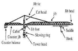
Tower cranes are a modern form of balance crane that consist of the same basic parts. Fixed to the ground on a concrete slab (and sometimes attached to the sides of structures as well), tower cranes often give the best combination of height and lifting capacity and are used in the construction of tall buildings. The base is then attached to the mast which gives the crane its height. Further the mast is attached to the slewing unit (gear and motor) that allows the crane to rotate. On top of the slewing unit there are three main parts which are: the long horizontal jib (working arm), shorter counter-jib, and the operators cab.
The long horizontal jib is the part of the crane that carries the load. The counter-jib carries a counterweight, usually of concrete blocks, while the jib suspends the load to and from the center of the crane. The crane operator either sits in a cab at the top of the tower or controls the crane by radio remote control from the ground. In the first case the operator''''s cab is most usually located at the top of the tower attached to the turntable, but can be mounted on the jib, or partway down the tower. The lifting hook is operated by the crane operator using electric motors to manipulate wire rope cables through a system of sheaves. The hook is located on the long horizontal arm to lift the load which also contains its motor.
Definitions:
Automatic safe load indicator:
It means a device intended to be fitted to a crane that automatically gives an audible and visible warning to the operator thereof that the crane is approaching its safe working load, and that automatically gives a further audible and visible warning when the crane has exceeded its safe working load (Regulation 3(1) of the LALGR).
Certified plan:
It includes drawings, details, diagrams, calculations, structural details, structural calculations, geo technical details and geo technical calculations which are certified by safety supervision personnel.
Competent person:
A competent person, in relation to any duty required to be performed by him under the LALGR, means a person who is -
a) appointed by the owner required by those regulations to ensure that the duty is carried out by a competent person; and
b) by reason of training and practical experience, competent to perform the duty (Regulation 3(1) of the LALGR).
Climbing frames:
Frames of a climbing crane, which transfer the loading from the crane on to the structure that supports it.
Climbing ladders:
Vertical structural frameworks by means of which some types of climbing cranes are raised.
Condition of tipping:
A condition when a crane is subject to an overturning moment which cannot be increased by even a small amount without causing the crane to fall over.
Free-standing height:
The maximum height at which a tower crane can operate without being held by ties or guys. Gauge The dimension between the inner faces of the rail heads of the rail track of a crane.
Height alteration:
It means climbing of a tower crane or the addition or removal of mast section to or from the main tower.
Overlapping zone:
An overlapping zone is the space which may be swept by the load, its attachment or any part of the tower crane, and common to at least two tower cranes.
Rail ties:
Ties used to retain rails at the correct distance apart and to withstand the imposed tensile and compression forces.
Wedges:
The means of securing the tower within tie frames or climbing frames of a tower crane.
Working space limiter:
A working space limiter is a limiting device to prevent the load, its attachment or any part of the tower crane from entering an overlapping zone.
Types of tower cranes:
Static and mobile tower cranes are available in a wide variety of types and configurations according to the particular combination of tower, jib and type of base which they employ.
Tower configurations:
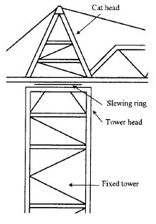
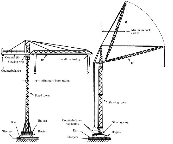
 Tower cranes are available with either fixed or slewing towers. On the fixed tower type the slewing ring is situated at or near the top of the tower and the jib slews about the vertical axle of the stationary tower. The slewing ring on the slewing tower type is situated at the bottom of the tower and the whole of the tower and jib assembly slew relative to the base of the crane. The towers can be further classified as being mono towers, inner and outer towers and telescopic towers.
Mono Towers :
The jib is carried by a single tower structure which may be either fixed or slewing. Provision may be made in the design to permit the tower to be extended.(Figure-1) .
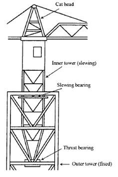
Inner and Outer Towers :
They are characterized by the jib being carried by a fixed or slewing inner tower which is supported at the top of the fixed outer tower. Provision may be made in the design to permit the outer tower to be extended.(Figure-2) .
Telescopic Towers :
The tower structure consists of two or more main sections which nest into each other to enable the height of the crane to be altered without the need for partial dismantling and re-erection. Telescopic
towers are usually of slewing type and more common on rail-mounted and mobile tower cranes.(Figure-3) .
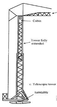
Mono tower Inner and outer Telescopic tower
(Figure-1) (Figure-2) (Figure-3)
Jib configurations :
The main types of jib used on tower cranes are horizontal trolley jibs, luffing jibs, fixed-radius jibs, rear-pivoted luffing jibs and articulated jibs.
Horizontal trolley jibs (“A” frame type) :
They are held in a horizontal or slightly raised position by tie bars or ropes connected to an “A” frame on the top of the tower crane. The hook is suspended from a trolley which moves along the jib to alter the hook radius. A suitable allowance needs to be made for deflection when calculating the clearance between adjacent cranes.
Horizontal trolley jibs (flat top type):
They are connected directly to the tower top and do not require tie bars or ropes connected to an “A” frame. This reduces the overall height of the crane. The hook is suspended from a trolley which moves along the jib to alter the working radius. A suitable allowance needs to be made for deflection when calculating the clearance between adjacent cranes.
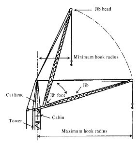
Luffing jibs :
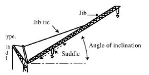
They are pivoted at the jib foot and are supported by luffing cables. The hoist rope which supports the load usually passes over a sheave at the jib head, and the hook radius is altered by changing the angle of inclination of the jib.
Fixed-luff jibs :
They are also mounted on pivots at the jib foot. Unlike the luffing jibs, these are held by jib-ties at a fixed angle of inclination. On some types, the hook is suspended from the jib head and the hook radius cannot be altered, whereas on others the hook is suspended from a saddle or trolley which travels on the jib.
Rear-pivoted luffing jibs :
The jib pivot of this type of jib is situated at the top and behind the center line of the tower and the hook is supported by the hoist rope which passes over a sheave at the jib head.
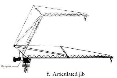
Articulated jibs :
The jib has a pivot point somewhere in its middle area. Some models are level-luffing; that is, the hook elevation remains constant as radius changes. It is possible to provide either a trolley or a fixed-location hook or even a concrete pump-discharge line. Articulated jibs are mounted on towers identical to those used with horizontal trolley jibs.


Mounting configurations:
Tower cranes are also characterized according to their mounting configuration. They are available as static bases, rail-mounted units and mobile units.
Static bases :
There are three main types of static bases.
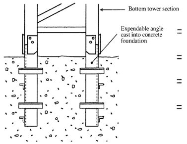
In-situ base :
The crane is mounted on special corner angles,frames or an expendable tower section, cast into the concrete foundation block.
On own base - The crane is mounted on its own base section or chassis which, without wheels and traveling gear, but with ballast, stands on a concrete base.
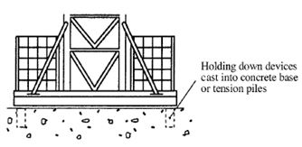
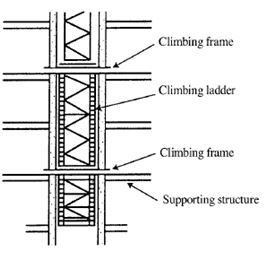
Climbing base - The crane is supported by the structure which it is being used to construct, and to which it is attached by climbing frames and wedges. The height of the cranes can be extended as the height of the structure increases by means of climbing supports attached to the frames. Climbing support can be metal ladders, rods or tubes. A climbing crane may be mounted initially on a fixed base and its support be later transferred to climbing frames and supports.
Rail-mounted units :
The cranes are mounted on a chassis frame which is supported on rail wheels. The wheels are usually double flange. When all wheels are removed, some tower cranes can be used as static based cranes .
Mobile units :
The mobile mounting configuration consists of truck mounted, wheel-mounted / crawler mounted units.
Truck-mounted tower cranes :
Tower cranes mounted on truck or lorry chassis are available. It is essential that this type of crane
has its outriggers extended. The outriggers should be securely set up and level on its jacks when handling loads.
Wheel-mounted tower cranes:
These are not normally self propelling and may be moved by towing by a suitable vehicle. They are provided with stabilizers or outriggers and jacks which should be set (and the wheels either removed or raised clear of the supporting surfaces) before commencing erection or lifting operations.
Crawler-mounted tower cranes:
There are two principal types of crawler bases used on this type of tower cranes. One is a twin track type which is mounted on one pair of crawler tracks. The crane requires outriggers to be extended and jacks set when handling loads. The other is the straddle-type which is mounted on four widely spaced crawler tracks, each of which can be adjusted to height. Both types of tower cranes should be set firm and level when handling their rated safe working loads. In general, they do not have the same freedom of mobility as for example crawler-mounted mobile cranes.Reference should be made to the crane specification and to the manufacturer regarding conditions under which these machines may travel in their erected state.
Types of static base for tower cranes
On own base
In-situ base Climbing base
Rail-mounted tower cranes
 a. With saddle jib and fixed tower b. With luffing jib and slewing tower
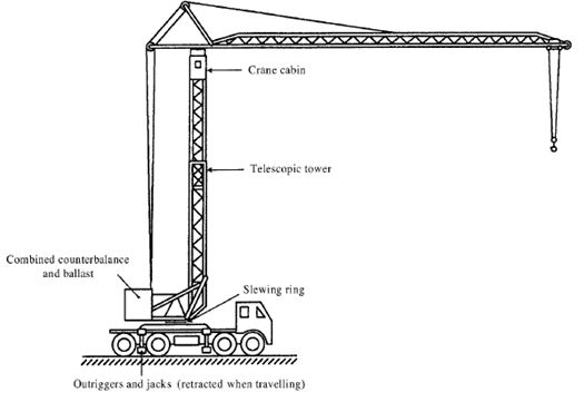

Fig. 2 Truck-mounted tower crane Fig. 3 Wheel-mounted tower cranes 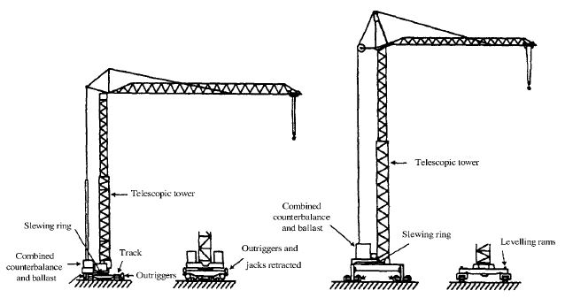 a. Twin track type Side view a. Four track straddle type Side view
Identification:
The crane should have a permanent durable plate bearing the manufacturer's name, machine model, serial number, year of manufacture and weight of the unit for identification purpose.
Every major structural, electrical and mechanical component of the machine should have a permanent durable plate / a clear indication bearing the manufacturers' name,machine model number, serial number, year of original sale by the manufacturer and weight of the unit. Besides, identification numbers should be clearly marked on all basic removable components and attachments
of the machine (such as counterweights etc.) to show that they belong to that machine. It is important that these components should be used only on that machine or identical models or equipment for which they were specifically intended by the manufacturer.
Automatic safe load indicator:
All types of crane, except those with a maximum safe working load of 1 tonne or less or those operate with a grab or by electromagnetic means, shall be fitted with an automatic safe load indicator (Regulation 7B of the LALGR). The automatic safe load indicator is usually used in association with overloading cutout devices. The specification of automatic safe load indicator should conform to British Standard 7262 or equivalent standards.
Operation Features of Tower Cranes:
Operating controls:
All controls must be located within easy reach of the operator and allow him ample room for operation. The controls should be of dead man switches in that they return to neutral automatically when released. The main power switch should be lockable and located within easy reach of the operator. Each control must be clearly labelled and marked to show the motion and the direction of
movement that it controls. Where practicable, controls should be arranged so that accidental displacement is prevented and inadvertent pressure on them does not cause the crane to be set into motion.
Guards and protective structures:
All exposed moving parts of a tower crane such as gears, pulleys, belts, chains, shafts, flywheels, etc. which might constitute a hazard under normal operating conditions shall be effectively guarded
Limiting switches:
All tower cranes of every configuration must be equipped with built-in safety devices which operate automatically to prevent damage to the machine should the operator make an error. The most important of these are the limit switches which would eliminate the possibility of crane overload or over-travel of crane components
Every tower crane must have :
- a hook height limit switch that causes the hoist drum to stop whenever the load hook reaches a predetermined maximum height position;
- luffing jib limit switches that cause the jib hoist drum to stop whenever the jib is raised to too high an angle or lowered to too low an angle. These switches should be adjusted by raising up and lowering down slowly (without load) and allowing the jib to come in contact with the striker switches;
- a trolley travel limit switch that causes trolley motion to stop whenever the trolley reaches a predetermined maximum out or maximum in position;
- an overload limit switch that causes the hoist drum to stop whenever the load being hoisted exceeds the maximum rated load for any radius or jib angle or whenever the over-turning moment exceeds the rated load moment. The overload limit switch should be installed in association with the automatic safe load indicator; and
- travel limit switches for rail mounted cranes that apply the carriage brake whenever the crane comes near the ends of the tracks.
Crane standing or supporting conditions:
(a)The ground or foundations, temporary supporting structures, grill ages, packing's, connections and anchorages for tower cranes should be of sufficient strength to withstand the maximum in-service and out-of-service loading without failure. In particular, suitable preparation of ground surface for fixed tower cranes should be carried out for safety reason.
(b) It is essential that the ground on which a tower crane stands has adequate bearing capacity. In assessing this, account should be taken of seasonal variations in ground conditions. The bearing capacity must not be exceeded under the most severe static and dynamic crane loading conditions.
(c) The siting of the crane, the assessment of maximum loads and the design of foundations, supporting structures and ancillary details should be certified by a safety supervision personnel. Particular care should be taken to ensure that the imposed loading's are not underestimated. Careful assessment of probable wind pressures should also be made, taking into account the degree of exposure of the site and any other special factors.
(d) Although tower crane manufacturer's instructions may specify maximum wind speed for service conditions, they cannot give recommendations for survival wind conditions on a particular site. On tall cranes, wind forces will have a considerable influence on the strength requirements of the supports and foundation.
Underground hazards:
(e) Cranes should not be sited where there is danger to their foundations, supporting structures from cellar whether filled or not, temporary shoring, excavations, embankments, buried pipes and mains, and etc. With these underground hazards, it may be necessary to provide additional special foundations to ensure the safety of the crane.
Tidal or flood water areas:
(f) In areas subject to tidal or seasonal flooding, or where there is a high water table, the crane may require deep foundations or special ground consolidation. In such situations, all machinery and electrical equipment should be positioned where it is not in danger from any rise in the water level. Unless adequate precautions are taken, the crane should not be sited where there is danger to foundations, rail tracks or temporary access roads from surface water drainage, flooding or rises in the water level.
Erection, Dismantling and Height Alteration:
General precautions:
Accidents may occur during crane erection, dismantling and height alteration operations due to failure to follow the correct procedures specified by the crane manufacturers, use of incorrect parts, the wrong size or type of bolt, the incorrect assembly or sequence of assembly, or taking apart of components. To avoid dangerous and expensive consequences, the following points should be
observed:
(a) the owner should arrange to conduct a risk assessment before the commencement of any erection, dismantling or height alteration operation on tower crane to identify the hazards inherent in the operation and the hazards which could result from adjacent activities, the risk assessment should be conducted in accordance with the details
(b) the owner should formulate measures for avoiding the hazards identified in risk assessment, or where this is not possible, devise measures for minimizing their likelihood of occurrence / mitigating their consequences. These measures include but not limited to the following:
- installation of fall protection system for workers working at height;
- suspension of work activities within an exclusion zone around the tower crane until an operation is completed;
- provision of personal protective equipment such as protective gloves, ear protectors and reflective vests;
- sufficient rest breaks;
- provision of proper training for competent person and workmen engaged in tower crane erection, dismantling or height alteration operations;
- provision of adequate lighting between floors; and ensure the work is carried out by competent workmen and competent person.
- all measures for avoiding or mitigating the hazards identified in the risk assessment;
- step-by-step procedures supplemented by diagrammatic illustrations;
- highlighting of critical hazards and safety precautions by specific warning words such as “Danger”, “Caution” and “Hold Points”;
- procedure and instruction on dealing with “Hold Points” of critical parts;
- procedures for avoiding hazards to personnel working adjacent to the tower crane;
- clear statements on the role and tasks of members of the working crew; and
- arrangements for effective communication;
(c) if applicable, copies of risk assessment report (including the method statement) should be distributed to the competent specialist contractor, who should be advised of the estimated duration of the operation and the boundaries of the exclusion zone;
(d)if practicable, erection, dismantling or height alteration operation during night time should be avoided;
(e) most manufacturers specify limiting wind velocities for the erection, dismantling and height alteration operations, and these operations should not be undertaken in high wind speeds. Particular care should be taken in gusty conditions and where there are shielding and funneling (venture) effects in the vicinity of tall buildings;
(f) assemblies should be slung from the points recommended by the manufacturer and in such a way that they will not swing or become unstable or sustain damage when lifted;
Erection of tower:
When the base or chassis has been set up, the tower (which may include the slewing gear and tower head) is then erected and attached to it using a second crane or a self-erection procedure. In either case the tower should be correctly orientated within the base section.
Where the jib is attached to the tower head before the tower is raised from horizontal to the vertical position, some means, such as a plank or board should be placed beneath the outer end of the jib to ensure that it can move freely across the ground as the tower is raised.
Where a second crane is used for erection, the number of sections in any tower sub-assembly should be minimum as to eliminate excessive stresses in the assembly when it is raised from the horizontal to the vertical position. It is recommended that jib-ties are attached before the jib is raised and positioned at the top of the tower section. When a tower section or sub-assembly has been placed in position, all bracing, locking devices, etc., should be attached and bolts securely tightened before proceeding with the next stage of the erection operation. It is essential to ensure that any specially strengthened tower sections are positioned where required.
It may be necessary to guy or support the tower depending on its free standing height. When tension the guys, ensure that the pull is even on each and that the tower remains perfectly plumb. Ensure also that blocking is installed in the tower to support the guys and to prevent the tower from being damaged.
Weather conditions:
Cranes shall not be used under weather conditions likely to endanger its stability. Before a crane is taken into use after exposure to weather conditions likely to have affected the stability of the crane, the crane's anchorage or ballast shall be tested by a competent examiner (Regulation 7G of the LALGR).
Any instructions issued by the crane manufacturers advising conditions under which a crane should be taken out of service and recommending the conditions in which it should be placed should be strictly followed. During adverse weather conditions such as rainstorm and lightning, adequate precautions should be taken to prevent personnel associated with the use of the crane from being
endangered.
Cranes are generally designed to operate in conditions of normal steady wind speed and should not be operated in wind speeds that are in excess of those specified in the operating instructions for the crane. Gusty wind conditions may have an adverse effect on safe working loads and machine stability. Even in relatively light wind conditions it is prudent to avoid handling loads presenting large wind-catching surfaces.
Name boards or other items presenting a wind catching area should not be fitted to the jib, counter jib, or tower of a tower crane without the express approval of the manufacturer.
An anemometer or wind speed measuring device should be provided at a suitably elevated position on all tower cranes. Where practicable the indicator of the instrument should be fitted at the crane operator's station. Necessary actions on the operation of tower cranes which correspond to various magnitudes of measured wind speed as recommended by the manufacturers should be strictly
adhered to.
Monthly Inspection and Maintenance of Tower Crane:
(1) Further to weekly full inspection by competent person, inspection and maintenance to tower crane(s) should be carried out at least once in a month by the inspection and maintenance technicians for tower crane.
(2) The inspection and maintenance technicians should properly record all their work performed and the respective findings.
(3) The record should be read and signed by inspection and maintenance technician(s).
(4) Inspection and maintenance record should include the following, if applicable:
- basic information such as crane model, the date of the inspection, workplace reference, workplace address, crane owner, wind speed, running hour of the crane and voltage of the power supply to the crane should be logged;
- details of inspection, maintenance and repair work carried out should be logged in the record with details of the condition of the parts inspected and whether lubrication was applied. If repair work is required or has been carried out, the details should be entered into the record;
- the inspection, maintenance and repair work carried out on critical mechanism of the tower crane, including but not limited to, if applicable:
(5) hoisting operation of the tower crane such as:
- inspection and adjustment (if required) of the braking system for hoisting, auxiliary hydraulic braking system, hook height limit switch, moment cutout switch and overload cutout switch;
- inspection of electrical parts for hoisting system, gearbox oil level and refill, hoist winch and main axle, lubrication and oiling;
- fixing of the base for hoisting parts, connection pins/bolts for gearbox and footings;
- inspection of the connections for all pulleys, hooks and pins;
- inspection of the lubrication, wear and tear condition of wire ropes;
- inspection of the swivel/anti-twist device for wire ropes at jib; and
- inspection of safety latches of all hooks;
(6) luffing operation of the tower crane such as:
- inspection and adjustment of hydraulic braking system, luffing travel limit switch and trolley limit cutout switch;
- inspection of electrical parts for luffing;
- fixing of luffing parts, pins bolt and nuts;
- inspection of the lubrication, wear and tear condition of trolley pulleys;
- inspection of the lubrication, wear and tear condition of wire ropes; and boom stops.
(7) slewing parts such as:
- inspection and adjustment to slewing limit switches;
- inspection of electrical parts for slewing;
- inspection and securing of V-Belt to the slewing motor;
- inspection of the slewing gearbox oil level and refill;
- inspection and fixing of the bolts of slewing bearing;
- lubrication of the slewing bearing with grease;
- lubrication of the slewing ring with grease; and fixing of connection pins/bolts for gearbox;
(8) steel structure and main structural parts such as:
- inspection of tower base and mast base;
- inspection of the connections of all mast sections, checking for any missing split pins / bolts and nuts;
- inspection of the connections and split pins at jib and other steel structural parts / bolts and nuts;
- inspection of the welding parts of all structural components such as mast sections, slewing ring, tie bar and foundation anchor etc.;
- inspection for any deformation at tower mast sections, jib and counter-jib (vertical parts and tie bars); inspection of the connections of climbing collars (or wall ties)
- inspection of pins and bolts of ballast blocks; and
- inspection of climbing ladders of tower crane; and
Routine checks:
At the beginning of each shift or working day, the operator, if competent for the purpose, or a competent person, should carry out the following routine checks, as appropriate:
a) checks as required by the manufacturer’s instructions;
b) check that the automatic safe load indicator is correctly set and/or fitted with the correct jib length
c) (or jib and fly-jib lengths) and falls of hoist rope;
d) check that the correct load-radius scale appropriate to the jib (or fly-jib) length is fitted on the visual indicator;
e) check crane level indicator (where applicable);
f) check working space limiter/anti-collision system (where applicable);
g) check audio and visual alarming devices;
h) check the security of the counterweight or ballast where this is in the form of removable weights, check that the weights fitted correctly correspond to those shown on the counterweight chart for the operating condition.
i) check the oil level(s), fuel level and lubrication;
j) check hook for signs of cracks and wear;
k) check loosening of pins, bolts and nuts;
L) check the ropes, and rope terminal fittings and anchorages for obvious damage and wear;
m) check the condition and inflation pressure(s) of tyres (where applicable);
n) check that all water is drained from any air receivers;
o) check the jib structure for damage;
p) check the operating pressures in any air and/or hydraulic system(s);
q) check leakage of brake fluid and hydraulic oil;
r) check the operation of the crane through all motions with particular attention to brakes to ensure that these are operating efficiently;
s) check the operation of all limit switches or cut-outs (use caution in making the checks in case of non-operation);
t) on rail-mounted cranes the wheels and axles are in good condition; the cable drum is free to revolve and the cable does not foul on any part of the crane structure;
u) all rail clamps and out-of-service anchorages have been released;
v) the track is in good condition and clear of obstructions, and that there is no undue settlement, loose joints, cracks, or gaps between adjacent length of rail;
w) the crane is placed out of service when the wind speed registered is near the manufacturer's safe working limit and that where an anemometer is fitted to the crane, it is in working order;
x) split pins and locking cellars are in position on jib and counter-jib ties and counter balance hanger bars;
y) the travel warning device operates;
z) on a climbing crane all climbing frames and wedges are secure, and that the anchorages and wedges on any tower ties or tie frames are secure and locked in position where necessary; and
Click the below link to download the tower crane safety checklist

Tower crane safety check sheet
Tower crane PM safety check sheet
Tower crane weekly and monthly check sheet