Introduction:
The purpose of this guidance is to give advice on precautions for the prevention of accidents in the use of abrasive wheels, in particular injury resulting from either wheel breakage or contact with a running wheel. For the duties of those people using abrasive wheels to be fully understood, the guidance should be read in conjunction with the Approved Code of Practice (ACOP).
The risk of breakage is inherent in every abrasive wheel. If the number of breakages is to be kept low, the initial care exercised in the design, manufacture and testing by abrasive wheel and machine makers must be coupled with the adoption of safety measures by the users. Accident statistics indicate that nearly half of all accidents involving abrasive wheels are due to an unsafe system of work or operator error.
Abrasive wheel characteristics:
An abrasive wheel is usually defined as a wheel consisting of abrasive particles bonded together with various substances. There are two main types of bonding agent: inorganic and organic.
Inorganic bonds are mainly vitrified, ie the wheel is generally fired in a furnace to give the bond a hard, strong but brittle structure. These wheels are used for precision grinding applications as they hold their shape, but require dressing.
Organic bonds are not fired but are cured at low temperature; the bond agents are resinous (B), rubber (R) and shellac (E). Such wheels are tough, shock-resistant and self-dressing, and are most suited to non-precision applications, for example fettling and cutting off.
The following words in bold are the variable elements in abrasive wheel manufacture.
(a) Abrasive means the type of abrasive used in wheel construction;
(b) Grain/grit size means the particle size of abrasive grains. The range is expressed by number (very coarse 4 to very fine 1200);
(c) Grade represents the tenacity with which the bonding material holds the abrasive grain in a wheel. Wheels are graded as ‘soft’ or ‘hard’ according to their degree of tenacity. The grade scale is expressed in letters from A (extremely soft) to Z (extremely hard);
(d) Structure means the level of porosity in the wheel. The higher the number, the greater the level of porosity;
(e) Bond type means the bonding material used in the wheel construction.
Abrasive wheel marking system:
Maximum permissible speed
13 The maximum permissible speed in revolutions per minute (rpm) and meters per second (m/s) specified by manufacturers should be marked on every abrasive wheel larger than 80 mm in diameter, or on the blotter or identification label which is sometimes attached to it. Since it is not practicable to mark smaller wheels, the maximum permissible speed in rpm of wheels 80 mm in diameter or less should be stated in a notice posted in a position where it can easily be read. For speeds of 50 m/s and above, color-coded stripes will appear on the wheel.
Restrictions of use
Specify how wheels should be marked to indicate specific restrictions for use. These are:
(a) RE1: Not permitted for hand-held and manually guided grinding;
(b) RE2: Not permitted for hand-held cutting-off machines (see Figure 1);
(c) RE3: Not suitable for wet grinding;
(d) RE4: Only permitted for totally enclosed working area;
(e) RE6: Not permitted for face grinding.

Figure-1
Shelf life
All organic bonded wheels for hand-held applications will bear a use-by date of three years from the date of manufacture.
Traceable number
A code number should be marked on the wheel to indicate the source and manufacturing details of the wheel.
Wheel breakage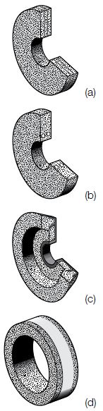
Abrasive wheel manufacturers take all reasonable precautions, including speed tests, to supply sound wheels, and various methods are used in their construction to reduce the risk of breakage. These include:
(a) Fibre reinforcement: This is normally a resin-coated, woven, glass-fibre mat used in organic wheels (resinoid and rubber bonded) for heavy-duty grinding and cutting operations. It allows the wheel to withstand high stresses and helps to contain fragments if the wheel breaks in use;
(b) Steel rings: These are moulded into the wheel close to the bore and are designed to retain wheel fragments if breakage occurs when the wheel is near to throwaway size. They can also be used to prevent excessive wear on the wheel;
(c) Safety inserts: These are threaded nuts incorporating locking teeth and form part of a plate which strengthens the base of a cup wheel used for portable grinding. They serve merely as an additional safety device and may not replace the guard;
(d) Tapewinding: Adhesive tape, glass-fiber or metallic wire may be used to strengthen thin-walled cup and cylinder wheels. In the event of breakage, they help to hold the fragments together;
(e) Fine grit center or similar: A fine grit center is placed around the bore to increase the strength of a vitrified grinding wheel. The center is molded together with the wheel. The bore area may also be impregnated by epoxy resin to increase the strength of the wheel. These two types of reinforcement are used for wheels operating at 63 m/s to 125 m/s.
In spite of these precautions breakage may occur in service due to a defect caused by subsequent misuse or handling. Bad storage, incorrect selection of a wheel, improper mounting, excessive out-of-balance conditions, excessive speed, grinding machine defects, and malpractices in the grinding operations are all factors that can result in breakage. Two or more of these factors may operate together, and it is essential that every breakage of a wheel should be followed by careful investigation, to establish the cause of the breakage and take suitable action to prevent a recurrence.
Examination, handling and storage of abrasive wheels
Examination
Wheels should be carefully unpacked, cleaned with a brush and examined for possible damage in transit. In unpacking, the careless use of a tool may cause damage to the wheel. The soundness of wheels can be further checked by tapping them with a light, non-metallic implement. This is known as the ‘ring’ test. Wheels must be dry and free from sawdust for the ring test otherwise the sound will be deadened. It should also be noted that organic bonded wheels do not emit the same clear metallic ring as inorganic bonded wheels. Heavy wheels should be supported on a clean hard floor for the ring test while light wheels should be suspended from their hole on a finger or small pin. If the wheel sounds dead, for example due to cracking, it should not be used.
Comparison with other wheels of the same lot and specification will allow rejection of any wheel with a suspiciously different ring before use. In case of doubt, the manufacturer should be notified. The ring test is not practicable with the following types of wheels because of their shape or size, so extra care and vigilance is required during the visual examination:
(a) small wheels (100 mm diameter and smaller);
(b) plugs and cones;
(c) mounted wheels;
(d) segments;
(e) plate-mounted wheels;
(f) inserted nut disc and cylinder wheels.
Handling
All abrasive wheels are relatively fragile. It should not be assumed that organic bonded wheels (resin, shellac, rubber) will stand rough handling. The following rules should be observed to avoid chipping, cracking and breakage:
(a) handle wheels carefully to prevent dropping or bumping. Do not roll abrasive wheels. Where this is unavoidable because of the large size of the wheel, a soft, resilient floor surface is essential.
(b) use trucks or suitable conveyors which will provide proper support for transporting wheels which cannot be carried by hand (Figures 2 and 3). Stack and support wheels carefully on trucks so that they will not topple over and be damaged. Do not pile heavy castings or tools on top of abrasive wheels.
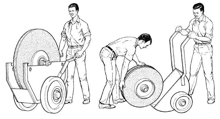
Figures 2 and 3 When handling large wheels use a truck or other suitable conveyance. They should not be rolled along the floor unless a suitable mat or other protection is available.
Storage
Suitable racks, bins or compartmented drawers should be provided to accommodate the various types of wheels used. The following suggestions covering the design of facilities may be helpful. Most plain and tapered wheels are best supported on their edges or on a central support.
21 Where the wheels are placed on their edges, the support should take the form of a cradle to prevent rolling, with a sufficient number of partitions to prevent wheels from falling over. To prevent warping, thin, organic bonded wheels such as those used for cutting-off should be laid flat on a horizontal surface of steel or similar rigid material away from excessive heat and moisture. Blotters or other packing should not be placed between stacked thin wheels. However, if the wheels are supplied with blotters attached, suitable separators should be used to preserve flatness. Cylinder wheels and large, straight cup wheels may be stacked on the flat side with corrugated cardboard or other cushioning material between them, or they may be stored in racks similar to those used for large, straight wheels. To prevent chipping of edges, taper cup wheels are best stored as shown in the illustration of a typical storage rack (Figures 4a and 4b).
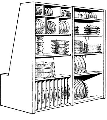
Figures 4a
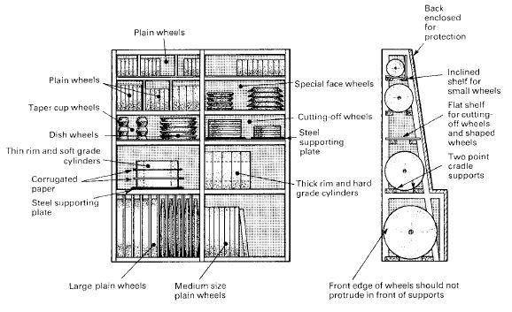
Figures 4b
To minimize deterioration, wheels must be stored in a room which is dry and not subject to extreme temperatures. It is recommended that wheels should be marked with the date they are received from the supplier. Older wheels should be issued before newer wheels and if there is any doubt, or if wheels have been in stock for more than three years, the manufacturer should be consulted about their suitability for use.
Selecting the correct wheel for the job is essential for safety. A grinding wheel may be dangerous if used for an application for which it is not intended. It is therefore essential that the fullest details of the type of grinding operation should be given to the manufacturer to enable the correct wheel to be supplied.
As a rough guide, soft wheels are preferred on hard material and hard wheels on soft material. With wheels of unsuitable structure for the job, ‘loading’ may result, ie the abrasive wheel face becomes clogged with particles of the material being ground. A wheel may also be either too hard or too fine, resulting in ‘glazing’. The operator is then tempted to use excessive pressure for the work on the wheel, a contributory cause of wheel breakage. Each type of wheel has its uses and is best suited to certain classes of work. The best policy in selecting grinding machinery is to consult machines and abrasive wheels manufacturers and not to experiment without competent advice.
Speed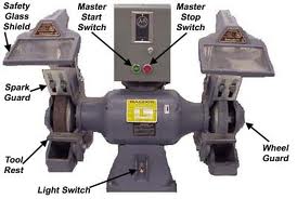
Remember that centrifugal force (the ultimate cause of wheel bursts) increases not directly with speed, but as the square of the speed. The speed at which the abrasive wheel revolves is, therefore, extremely important. It cannot be too strongly emphasized that doubling the speed increases fourfold the stress in the wheel and hence the risk of the wheel bursting.
Peripheral and rotational speed
The maximum operating speed is marked on every wheel in two ways:
(a) the peripheral surface speed which is given in m/s;
(b) the rotational speed which is given in rpm.
As the wheel wears down in use, the effective peripheral surface speed will reduce if the rotational speed remains constant and may result in a reduced grinding efficiency. To counteract this, the spindle speed can be increased, providing the maximum peripheral surface speed of the wheel is not exceeded. Always ensure that the spindle speed is reduced to its original value before fitting new wheels.
Never operate new abrasive wheels at speeds (in rpm) in excess of that marked on the wheel. Overspeeding is one of the main causes of wheel breakage. To illustrate the point, a fragment from a burst wheel operating at 35 m/s is travelling at 80 mph (126 km/hr) and for 125 m/s at 280 mph
(450 km/hr).
Grinding machine
Abrasive wheels should not be mounted on makeshift apparatus. They should be mounted on the type of machine for which they are intended. These appear to be obvious precautions, but accidents still occur because wheels are mounted on home-made or improvised apparatus quite unsuitable for the work. Likewise, accidents are caused by heavy wheels being fitted to spindles designed to take only the lightest of wheels. As a result, vibration is excessive and breakages occur. On no account should an abrasive wheel be screwed on to the tapered spindle of a buffing machine. This dangerous method of mounting is likely to result in the breaking of the wheel owing to the wedging action of the tapered spindle.
Pedestal grinders should be heavily built and mounted on good foundations. Bench grinders should be securely anchored to a stout bench.
Spindles
The spindle should be long enough and threaded to a sufficient length to ensure that when the wheel and flanges are mounted, there will be enough thread for full engagement of the nut on the spindle. The thread should extend inside the flange but not into the hole in the wheel. When the wheel is secured by means of a single central spindle nut, the thread should be such that the direction of tightening the nut is opposite to the direction of rotation of the wheel to ensure that the nut will not come loose as the wheel rotates.
Machine bearings
Machine bearings should be maintained in good condition, free from play and adequately lubricated. Loose bearings or any other factor causing an out-of-balance condition will produce vibration and may cause the wheel to knock against the work excessively with the eventual risk of wheel breakage. In addition, heat generated by machine bearings in poor condition can be transmitted to the spindle causing thermal expansion which may result in cracking of the abrasive wheel.
Speed control
In no circumstances should the maximum permissible operating speed specified by the wheel manufacturers be exceeded.The maximum speed of the spindle should be marked on every grinding machine so that it is easy to compare the speed marked on the wheel with the speed of the machine spindle. Where the spindle can be operated at more than one specific speed, each speed must be shown, and if the speed is infinitely variable within a specified range, the notice must show the maximum and minimum speeds.
Insufficient power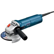
Inadequate power at the grinding wheel may be caused by a belt slipping or a driving motor of insufficient power. This will cause the wheel to slow down when grinding starts. The operator may apply greater pressure on the workpiece against the wheel and increase the stresses in the wheel. Flat spots will tend to develop and cause ‘bumping’ and breakage of the wheel.
Stopping devices
Means for starting and stopping grinding machines should be clearly visible and marked, placed in a safe position and within easy reach of the operator. On portable machines the control should be located so that there is no risk of accidental starting when the grinder is placed on a flat surface.
Mounting of abrasive wheels
The danger of an abrasive wheel bursting is considerably increased if it is not properly mounted; many accidents could be prevented if the people mounting the wheels were instructed in the hazards arising from incorrect mounting and in the correct method of assembly. Paragraphs 46–90 explain the purpose of the various components used with abrasive wheels and the precautions which should be taken in the mounting of each type of wheel.
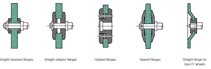
Figure 6 Basic types of mounting
The major stresses produced in an abrasive wheel under operating conditions tend to become greatest near the hole. It is therefore important that stresses due to mounting and driving are as far from the hole as practicable. This is done by recessing the side of the flange next to the wheel. In the case of straight adaptor and hubbed flanges there is an undercut in place of a recess . With certain exceptions, every abrasive wheel should be mounted between flanges which are at least one third of the diameter of the wheel.
The exceptions are:
(a) mounted wheels and points;
(b) wheels with threaded inserts;
(c) abrasive discs (inserted nut discs and cylinders);
(d) plate-mounted wheels;
(e) cylinder and cup wheels and segments mounted in chucks;
(f) wheels of 20 mm diameter or less.
Recess and undercut
Flanges should be recessed on the side next to the wheel. An exception is the single flat flanges used with threaded-hole wheels. Flanges for wheels with large holes, adapter and rubbed flanges are illustrated in Figure 6. These are not recessed, but the corners of the wheel seating should be undercut so that there will be no bearing on the side of the wheels within 6 mm of the hole.
Uniformity of diameter
As a general rule both the flanges used to secure a wheel to the spindle should be the same diameter and have the same recess diameter to create equal bearing surfaces on the wheel, but the shape of some wheels may not allow this rule to be followed, for example certain internal and cup wheels
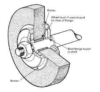
Blotters
Blotters of compressible material (usually cardboard not less than
0.2 mm thick and not more than 1.0 mm) as supplied by the wheel or machine manufacturer, should be used between the wheels and their flanges, except for the wheels mentioned in paragraph 56. The main purpose of blotters is to distribute the clamping force of the flanges evenly on the wheel, but they also prevent slipping at lower clamping forces and reduce wear on flanges. Blotters should be an easy fit on the spindle or on the wheel locating spigot, if there is one, and should be slightly larger than the flanges. Care should be taken to see that each blotter is free from wrinkles. If the wheel has been used previously, any pieces of old blotter or loose grains of abrasive should be carefully removed, otherwise high spots will occur leading to severe local stresses when the wheel is clamped tight. A blotter can serve as a label; however, a label cannot act as a blotter. Figure-7
Blotters should not used with the following types of wheels: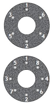
(a) mounted wheels and points;
(b) abrasive discs (inserted nut discs and cylinders);
(c) plate-mounted wheels;
(d) cylinder wheels mounted in chucks;
(e) rubber-bonded cutting-off wheels 0.5 mm or less in thickness;
(f) taper-sided wheels;
(g) wheels with threaded inserts.
Wheel bushes
Bushes are inserts made of plastics or metal and used to reduce the hole size in an abrasive wheel so that it can be mounted correctly on a small diameter spindle. Bushes are hand-pressed into the hole of the wheel and are not recommended for use with wheels fitted to portable grinding machines. They should be slightly less than the width of the wheel and blotters. As the power required to drive a grinding wheel is transmitted to it through the flanges, care should be taken to ensure that the bearing area of the flange is in contact with the wheel and not the bush.
Before using wheel bushes, the depth of the recess in the securing flanges should be measuredto see if it is possible for the bush to slide out of the wheel and become loose in the recess of the flange. This is most likely to occur when two narrow bushes are used one at each end of the hole as an alternative to one bush extending the full width of the wheel. If the depth of the recess will allow this to happen, the bushes should not be used and a wheel with a hole to suit the machine spindle should be used.
Starting new wheels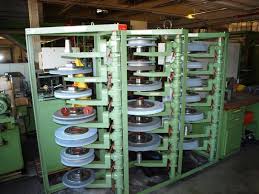
Before the wheel is run, the guard should be properly adjusted and secured. If the machine is fitted with a work rest, it should be adjusted as close as possible to the wheel and the wheel should then be rotated by hand to ensure that it is clear all the way round. New or re-fitted wheels should be run free at full operational speed for a short period before they are used, and during the trial run everyone shoud stand clear. With portable machines the operator should ensure the machine is operated with the guards properly positioned.
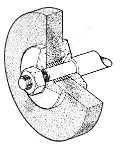
Plain wheels with small holes
Figure 8 shows a wheel correctly mounted. The wheel is gripped between two flanges of equal diameter, the inner (driving) flange being keyed on the spindle and the outer one tightened by a nut on the threaded spindle end. Excessive tightening of this nut is unnecessary and, by setting up an undue crushing stress in the wheel, might cause breakage. Each flange has an equal recess and the blotters are slightly larger than the diameter of the flanges.
Figure 9 shows a wheel incorrectly mounted. Here the flanges are not recessed and blotters are not used. The result may be that when the nut is tightened, proper gripping is not obtained even with normal pressure and localised stresses are set up near the hole. Other unsatisfactory and dangerous conditions which are sometimes found include: flanges unmatched in outside diameter and diameter of recess; one flange omitted and the nut tightened directly against the wheel; use of an ordinary washer as a substitute for a properly recessed flange. Such conditions increase the liability of a wheel to fracture because they result in undue concentration of stress near the hole.
Figure-8 Figure-9
Guards
Purpose of guards
In spite of the care exercised by abrasive wheel manufacturers in the design, manufacture and testing of wheels, the risk of a burst is inherent in every abrasive wheel and a guard of adequate strength must be provided to prevent injury from flying fragments.
A guard has two main functions: firstly to contain the wheel parts in the event of a burst; and secondly to prevent, as far as possible, the operator from coming into contact with the wheel. A guard also has the secondary functions of protecting the wheels against inadvertent damage and preventing an oversize wheel from being fitted.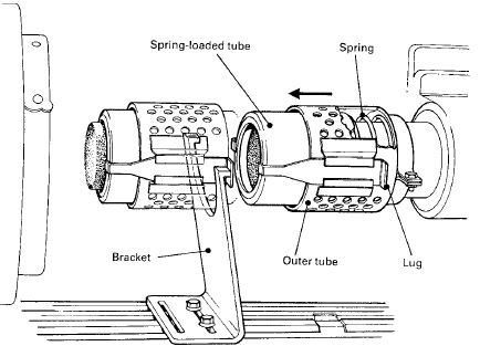
Internal grinding wheels are, while operating, guarded by the workpiece itself. On fixed internal grinding machines, however, arrangements can be made so that a guard may be placed in position automatically when the wheel in motion is withdrawn from the work (Figures 10 and 11).
Figure 10 A spring-loaded telescopic guard for use on an internal grinding machine. As the workpiece advances towards the wheel the bracket strikes the lugs and retracts the guard to expose the wheel. When the work is withdrawn, the guard is returned by the spring to its original position covering the wheel.
Figure-10
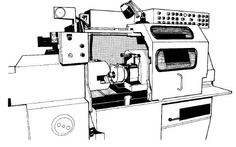
The internal grinding machine in Figure 11 is enclosed to control the emission of noise, vapour and splash. The sliding door is interlocked to ensure that access to the workpiece is prevented until it has stopped rotating. The abrasive wheel is guarded by a pneumatically operated telescopic guard which retracts and extends like the mechanical guard shown in Figure 10. The valves controlling the movement of the air cylinder are operated by a cam attached to the traversing table. Figure 11 shows the guard retracted to expose the wheel while shows the guard fully extended to cover the wheel.
Figure 11
Another example of guard design can be seen in Figure 12 where an energy absorbent foam lining is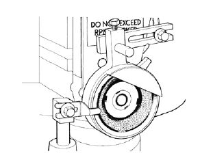 contained inside a light sheet-metal housing. This combination can, in some circumstances, be as effective as a heavier all-metal guard. Guards of this kind should only be used after extensive tests involving the bursting of an abrasive wheel have been conducted in safe conditions. (Figure-12)
The aim is to enclose the wheel to the greatest possible extent, and to keep the opening as small as possible, consistent with the nature of the work. To compensate for the increased exposure caused by wheel wear, either an adjustable vizor is provided (Figure 13) or the guard is constructed so that it can be adjusted manually as the wheel wears down. The guard has side members to limit the exposed area of the wheel and to contain flying fragments. It is usually necessary to construct the outer side member with a hollow boss which will enclose the projecting spindle and nut. When 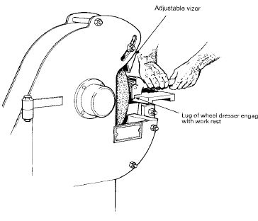 aguard is constructed from several component parts, the fastening should be strong enough toprevent disintegration of the guard in the event of a burst and the dangerous projection of the various parts into the surrounding working area. (Figure-13)
The entire assembly should be securely anchored to the machine frame. Accidents have occurred when guards, though robust, have been attached to the frame by bolts of inadequate strength, with the result that a burst wheel has projected the entire guard bodily from the machine.
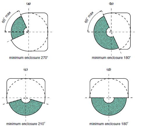
Figure 14 Wheel enclosure
angles for various fixed machines (the dotted line\ indicates an alternative guard profile)
(a) Bench and pedestal grinder
(b) Cylindrical grinder
(c) Stationary cutting-off and peripheral surface grinder
(d) Swing frame and highpressure grinder
Figure 14
To protect against this hazard it is advisable to provide substantial steel plates high enough around the table to contain any flying components. In some industries, such as the stone industry, where large wheels may be used with a long horizontal traverse between the wheel and the work, some additional enclosure, other than ordinary wheel guards, is desirable around the machine to restrict the exposure of the wheel below the guard to a minimum.
Wheel guards for portable machines
Guards for portable machines should be so designed that in the event of a wheel bursting / breaking, the guard remains attached to the machine (see Figure 15). The design and construction of the clamp should allow the guard to be positioned directly between the wheel and the operator. The clearance between the inside of the guard and the periphery of an unused wheel should not be greater than 6 mm.
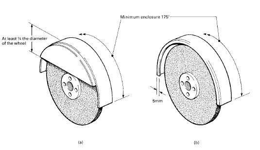
Figure 15
Alternative types of guards for reinforced depressed-centre cutting-off wheels and reinforced straight sided wheels other than cutting-off wheels over 130 mm used on portable machines
Wheel enclosure angles for portable machines
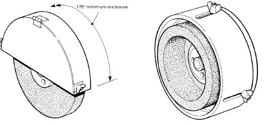
Reinforced depressed-centre, cutting-off wheels and reinforced straight-sided wheels other than cutting-off wheels. (Figures 16 and 17)
A guard for these wheels should have a minimum enclosure of 175 deg. and the side towards the machine should be covered by the guard. When the machine is in use the guard should always be positioned between the operator and the wheel. If the wheel is larger than 130 mm diameter the guard should have a front lip of at least 5 mm or a curtain segment with a minimum height of one quarter of the diameter of the wheel.
Non-reinforced straight-sided wheels (Figure 33)
At least 175o of the abrasive wheel periphery, and both sides, should be covered by the guard. The front curtain should be designed to facilitate easy replacement of the wheel.
Cup wheels (Figure 34)
These should be provided with an adjustable guard which covers the periphery and back of the wheel. The guard should be adjustable to compensate for wear of the wheel and to restrict the wheel exposure to a minimum.
Figures 16 Figures 17
Figure 16 A wheel guard for use with a non-reinforced straight-sided wheel on a portable machine
Figure 17 An adjustable band-type guard for straight and taper cup wheels mounted on a portable machine.
Portable and hand-held
grinding machines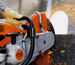
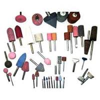
The largest number of abrasive wheels used are those found on hand-held machines. These machines are often used by people who have a wide range of skills, from the domestic user to the skilled tradesman, with the predominant user being semi-skilled. Only organic-bonded wheels should be used. Those intended for cutting-off operations should additionally have some form of reinforcement, usually fiber glass. The only exception is for the use of vitrified mounted wheels and points (see Figure 5, page 13, for wheel shapes).
The general safety precautions for abrasive wheels apply equally to all wheels used on all classes of portable machine. It is important that all machine guards are secured in place and are adjusted so that the guard is between the user and the rotating wheels. Serious, often fatal, accidents have happened when a guard is removed to allow an oversize wheel to be mounted on a machine. The unguarded wheel will be running at a speed in excess of the wheel manufacturer’s recommended maximum with the consequent risk of a wheel burst.
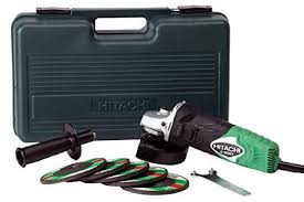
Electric grinding machines
These are the most common machines on which abrasive wheels are mounted. Electrical safety must be considered as well as the safe use of the wheel.
These tools are classified according to the way in which protection against electric shock is provided. For Class I tools, accessible metalwork has to be effectively earthed so as to provide protection for the operator if the metalwork is made ‘live’ because of an internal fault. For Class II tools, marked with the symbol , protection is provided by the use of all insulated or double insulated construction, and accessible metalwork should not be earthed.
Cables and connectors
Hand-held tools are often required to withstand constant handling and rough usage, and the conditions of use should be taken into account when selecting flexible cables for the tools. Cables manufactured to British Standard 6500: 2000 Electrical cables,11 with an abrasion-resistant sheath would satisfactory for normal use,but where the cable is vulnerable to damage,additional precautions such as heavy-duty sheathing or protective braiding will be necessary.
In the case of single-phase tools, two-core cable is suitable for Class II tools, but for Class I tools, a three-core cable is essential. The cable should be connected to the supply by a properly constructed connector, such as a plug and socket. For Class I tools the connector should incorporate an effective means of maintaining earth continuity, for example an earth pin or a scraping earth (ie a sliding connection between the earthed metalwork on the plug and the earthed metalwork on the socket).
Inspection and maintenance:
Routine checks, regular inspection and preventive maintenance are essential if accidents are to be avoided. An efficient maintenance system will also reduce days lost due to tools being out of commission.
The user of a hand-held tool should carry out a visual check on the tool before using it so that obvious defects can be identified, for example damage to the cable sheath, loose plug connections etc. Any tool in an serviceable or unsafe condition must be withdrawn from use until defects have been rectified by a person competent to carry out this class of work.
Routine visual checks are in addition to and are not a substitute for planned maintenance of hand-held tools.
All tools should be accompanied by specific instructions from the manufacturer. If there are no instructions, the following system of planned maintenance is recommended. All hand-held apparatus, including extension leads, should be identified by a serial number which should be recorded in a register. The register should indicate how often each item should be recalled for inspection. The recommended frequency of checks, inspection and testing for portable electric grinders is:
(a) For 110-volt machines the user is to carry out:
(i) a weekly safety check;
(ii) a formal visual inspection (eg a detailed inspection by a person competent to do so);
(iii) a combined inspection and test every three months (eg a detailed inspection and tests by a person competent to do so).
(b) For 240-volt machines the user is to carry out:
(i) a daily safety check;
(ii) a formal visual inspection every week (eg a detailed inspection by a person competent to do so);
(iii) combined inspection and tests before first-time use and then every month (eg a detailed inspection and tests by a person competent to do so).
Operation of abrasive wheels
Truing and dressing
The operator’s fingers may become trapped between the work-rest and the wheel, or the work piece being trapped in a similar way. Although such accidents are more frequently caused by poor adjustment of the work rest, their possibility is minimized by frequent truing to keep the wheel concentric on its spindle. A wheel ‘out-of-round’ will cause excessive vibration and periodic knocking of the work against the wheel. This will invariably result in damage to the abrasive wheel surface, such as ‘loading’ or ‘glazing’, which impair the cutting action and may induce the operator to compensate by additional pressure of the work piece on the abrasive wheel. Dressing the wheel is therefore essential for efficient production, and frequent light dressings are generally preferable to occasional severe dressings. The following important precautions should be taken:
(a) hand dressers should be properly supported so that leverage may be applied without undue effort;
(b) with a dresser of the revolving cutter type, the lugs provided as an anchor should always be used (Figure 13);
(c) haphazard methods of dressing, such as the use of a chipping hammer, or even striking the work against the wheel, should be forbidden;
(d) care should be taken to prevent the possibility of dressing tools becoming jammed between the abrasive wheel and work rest or any fixed part of the machine;
(e) it is important that the work rest is in good condition before wheel dressing and it is helpful to fit a spare rest with a straight edge especially for this purpose.
There are many types of abrasive wheel dressers, and various methods by which these operations may be carried out. If necessary, wheel and machine manufacturers should be consulted on the technical aspects of the subject.
Wheel balance
Abrasive wheels are balanced by the manufacturers within normal limits but after they have been taken into use, wheels used for off-hand grinding can become out of balance if they are not frequently trued. If the out-of-balance force is allowed to become excessive, it may result in damage to the wheel and spindle. For precision grinding, closer limits of balance may be required and this is obtained by various methods such as the use of heavy paint or by an arrangement of sliding weights which are incorporated in the flanges or collet. Adjustment of the sliding weights is normally done with the wheel assembly removed from the machine, on a balancing arbor and stand. An accelerometer probe is placed in contact with a fixed part of the machine near the wheel and a measure of the out-of-balance force is then shown on a meter.
Side grinding
Grinding on the side of a straight-sided wheel used for off-hand grinding is dangerous, particularly when it is appreciably worn or when sudden pressure is applied. However, for certain precision grinding operations it may be necessary to allow the side of the wheel to lightly touch a face adjoining the surface being ground, for example the thrust face on a stepped shaft, and in this case the side of the wheel may be lightly dressed with a diamond to create a shallow relief. Excessive dressing could however create a dangerously weak section which may cause the wheel to break under side loading or due to centrifugal force.
Personal protective equipment
To comply with the Personal Protective Equipment Regulations 199217 and other regulations, for example the Control of Substances Hazardous to Health Regulations18 and the Control of Noise at Work Regulations 2005,19 appropriate protection must be worn. People who use abrasive wheels on any type of machine are exposed to a number of risks:

(a) Injury to the eyes from flying abrasive and metallic particles,
(b) Inhalation of dust from dry grinding operations (for example petrol-engines cutting-off machines);
(c) Physical injury due to flying wheel fragments or ejected work pieces;
(d) Noise and vibration;
(e) On construction sites there will be a need for head protection as well as for feet and hands in addition to the other precautions mentioned.
Eye protection should conform to the relevant BS EN standard such as BS EN 166 Personal eye protection. Specifications;20 BS EN 167 Personal eye protection. Optical test methods;21 and BS EN 168 Personal eye protection.
Dust protection (face masks) etc should comply with BS EN 149 Respiratory protective devices.
Loose clothing Loose clothing such as ties or coat sleeves are easily drawn in between the wheel and the work piece and should not be worn. Rags and waste should not be used near a revolving wheel as they may also become entangled.
Supervision Frequent checks should be made by management to ensure that the safety precautions.
Click the below link to download more details about grinding wheel

Abrasive wheel - Safety Guidelines
Dos and Don ts - Abrasive wheel
Safety check sheet - Abrasive wheel
Power Point Presentation - Abrasive Wheel